
- special pliers for installing clamps for fastening CV joints or sliding pliers;
- puller of external locking rings;
- grease for CV joints 80 cm³;
- new hinge cover;
- new retaining and thrust rings of the hinge.
Removing
1. Remove the drive assembly (see "Front wheel drive - removal and installation").
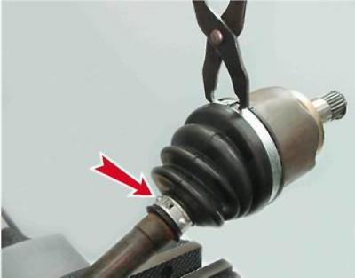
2. We fix the drive assembly in a vice and remove the large and small clamps of the protective cover with special pliers or sliding pliers.
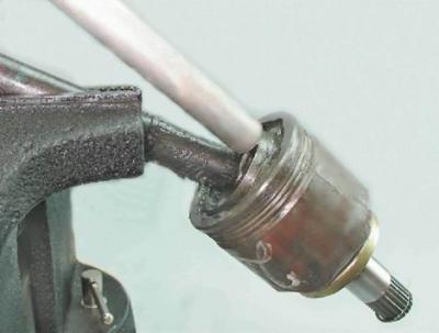
3. Using a slotted screwdriver, pry off and remove the protective cover from the body of the inner hinge.
Tip: A damaged cover can be removed by cutting it open with a knife.
Warning! When performing the following operation, if the hinge is to be reused, do not strike the separator or the hinge body.
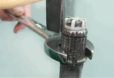
4. We fix the drive shaft in a vice. By striking with a hammer through a soft metal drift on the inner race of the hinge, we knock the hinge off the drive shaft.
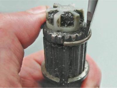
5. Remove the retaining and thrust rings, in the same way as shown on the outer hinge (see "External hinge of the drive - removal, replacement of the protective cover and installation").
6. Remove the protective cover from the drive shaft.
7. We wash the hinge in kerosene, wipe it with a clean cloth and let it dry.
Installation
1. We fix the drive shaft in a vice in a vertical position.
2. We wind the adhesive tape (or electrical tape) on the splines of the shaft, put a new protective cover on the shaft, move the cover to the middle of the shaft and remove the adhesive tape.
Note: On the right drive, turn the cover inside out onto the shaft.
Tip: Do not use a socket head to install the thrust ring. The internal chamfer, found on almost all heads, will compress the ring, which will not allow it to be installed on the shaft.
3. Using an open end wrench by 24 mm as a mandrel, we install a new thrust ring on the splined end of the shaft.
4. Using a slotted screwdriver, install a new retaining ring on the shaft.
5. We apply grease for CV joints to the shaft splines.
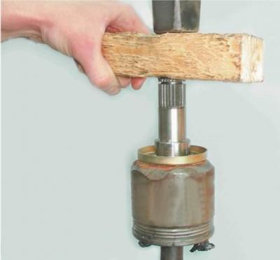
6. We put on the inner race of the hinge on the splines of the shaft. Align the hinge body with the axis of the shaft. With hammer blows through a wooden block, we press the hinge onto the shaft until the retaining ring is fully installed.
Warning! The inner joint requires 80 cm³ of grease.
7. We fill the hinge with grease for CV joints, and the rest of the grease (from 80 cm³) put in a protective case.
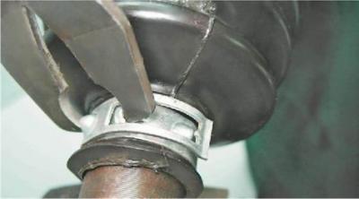
8. We put a large sealing belt of the protective cover on the hinge body, and install a small sealing belt of the cover into the groove of the shaft. Raising the small sealing belt of the cover with a thin slotted screwdriver, we release air from the internal cavity of the protective cover.

9. Using special pliers or large sliding pliers, install the large and small clamps of the protective cover.
Recommendation: Before installing the assembled drive to the vehicle, be sure to install a new retaining ring on the splined shank of the inner joint.
10. Install the drive assembly on the car (see "Front wheel drive - removal and installation").