




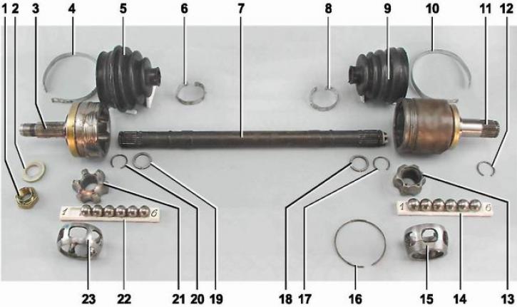
Left drive details: 1 - hub nut; 2 - nut thrust washer; 3 - outer hinge housing; 4 - large clamp of the outer hinge boot; 5 - protective cover of the outer hinge; 6 - small clamp of outer hinge boot; 7 - drive shaft; 8 - small clamp of the inner hinge boot; 9 - Inner hinge protective cover; 10 - large clamp of the inner hinge boot; 11 - inner hinge housing; 12 - retaining ring of the inner hinge shank; 13 - inner race of the inner joint; 14 - inner joint balls; 15 - inner joint separator; 16 - inner hinge lock; 17 - inner joint cage retaining ring; 18 - thrust ring of the inner joint cage; 19 - thrust ring of outer joint cage; 20 - outer joint cage retaining ring; 21 - inner race of the outer joint; 22 - outer joint balls; 23 - outer joint separator
Note: The right drive shaft is longer and made of pipe.
Each drive consists of two constant velocity joints (CV joints) and a shaft connecting the hinges. The short shaft of the left drive is made of a steel rod, the long shaft of the right drive is made of a steel pipe. The tail of the inner hinge housing is connected to the differential axle gear using a splined connection. The hinge transmits torque to the drive shaft regardless of the angle between the hinge housing and the shaft. The inner hinge is designed so that it not only transmits torque at different angles, but also allows for mutual axial movement of the hinge housing and the suspension drive shaft during movement. The outer hinge transmits torque from the drive shaft to the hub of the drive wheel, to which it is connected using a splined connection. The splined end of the outer hinge housing is attached to the hub using a nut. The hinges are protected from dirt and moisture by protective rubber covers secured with steel band clamps.
Note: The following describes the operations for removing, repairing and installing the left drive. All work on the right drive is performed similarly.
The text is copied from the online resource VAZBOOK