




The engine is specially designed for transverse placement on a front-wheel drive vehicle. The layout and main dimensions of the engine are chosen so that it, together with the gearbox, can be placed transversely in the engine compartment between the mudguards of the body.
The power unit - the engine with gearbox and clutch - is mounted in the engine compartment of the car on three rubber-metal supports.
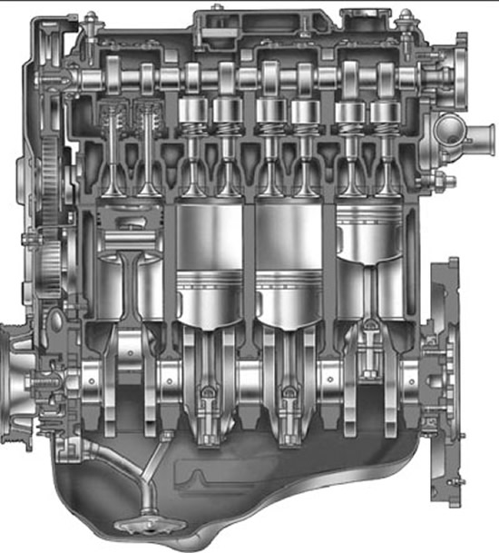
4.1. Longitudinal section of the VAZ-2111 engine
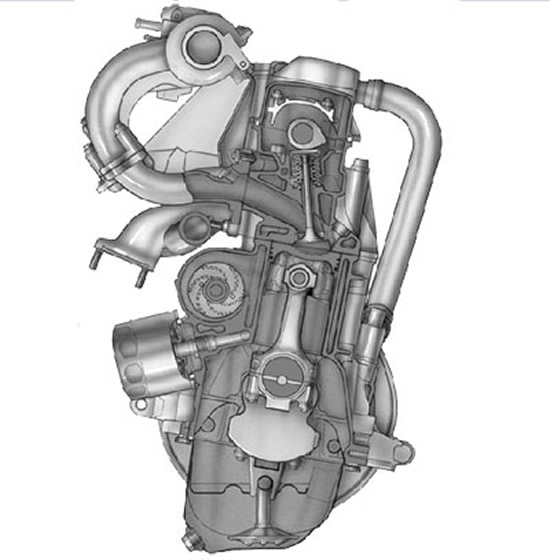
4.2. Cross-section of the VAZ-2111 engine
The cylinder block is cast from special high-strength cast iron, which makes the engine structure rigid and strong. The cylinders are made in one piece with the block. In the lower part of the cylinder block there are five main bearing supports with removable covers. The main bearing covers are attached to the cylinder block with bolts. The bearing holes are machined together with the covers, so the covers are not interchangeable and are marked with risks on the outer surface for distinction. The middle support has two seats for thrust half rings, which hold the crankshaft from axial movements. A steel-aluminum half ring is installed in front of the main bearing cover, and a metal-ceramic half ring is installed at the rear so that the grooves on the half rings face the crankshaft. The main and connecting rod bearing liners are thin-walled steel-aluminum. The upper main bearings of the first, second, fourth and fifth bearings have grooves on the inner surface, the lower main bearings and the upper bearing of the third bearing have no groove. The inner surface of the connecting rod bearings is smooth, without grooves.
The crankshaft is made of high-strength cast iron and has five main and four connecting rod journals. Eight counterweights located on the crankshaft serve to reduce vibrations. To supply oil from the main journals of the crankshaft to the connecting rod journals, oil channels are drilled in the crankshaft and closed with plugs. In addition to supplying oil to the connecting rod journals of the crankshaft, these channels also serve to clean the oil. Under the action of centrifugal force, solid particles and resins that are not captured by the filter element of the oil filter are thrown to the plugs.
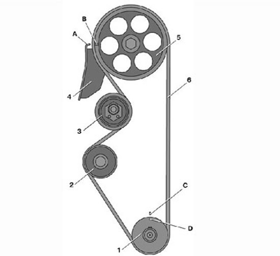
4.4. Camshaft drive diagram: 1 – toothed pulley of the crankshaft; 2 – toothed pulley of the coolant pump; 3 – tension roller; 4 – rear protective cover; 5 – camshaft toothed pulley; 6 – toothed belt; 7 – tension roller axis; A – mounting protrusion on the rear protective cover; B – mark on the camshaft pulley; C – mark on the oil pump cover; D – mark on the crankshaft pulley
The leading gear of the oil pump is mounted on the front end of the crankshaft, and a toothed pulley 1 is mounted on a segment key (see fig. 4.4) to drive the camshaft and water pump. In addition, a generator drive pulley or damper is installed on the front end of the shaft. A flywheel is attached to the rear end of the crankshaft with six bolts through a common washer. It is cast from cast iron and has a pressed-on steel toothed ring designed to start the engine with a starter. The connecting rods are steel, I-section, machined together with the covers. The cylinder number is applied to the connecting rod cover and the connecting rod itself. A steel-bronze bushing is pressed into the upper head of the connecting rod. The piston pin is steel, tubular section, floating type. It is fixed from longitudinal movement by two retaining spring rings located in the grooves of the piston boss. The piston is made of aluminum alloy. On the piston bottom there is a recess for the combustion chamber and two recesses for the valves. The piston skirt is conical in longitudinal section and oval in transverse section. Three grooves for piston rings are machined in the upper part of the piston. The groove of the oil scraper ring has holes that serve to drain oil collected by the ring from the cylinder walls into the piston. The piston rings are located in the piston grooves. The two upper rings are compression rings. They prevent gases from breaking through into the engine crankcase and help remove heat from the piston to the cylinder. The lower ring is an oil scraper ring.
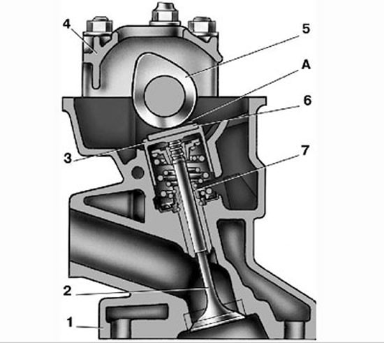
4.3. Valve drive mechanism: 1 – cylinder head; 2 – valve; 3 – pusher; 4 – camshaft bearing housing; 5 – camshaft; 6 – adjusting washer; 7 – oil deflector cap; A – clearance between cam and adjusting washer
The cylinder head 1 (Fig. 4.3), common to all engine cylinders, is made of aluminum alloy. The head is centered on the cylinder block with two bushings and secured with bolts. Channels are cast in the lower part of the head, through which the liquid that cools the combustion chambers circulates. The camshaft 5 is installed in the upper part of the head, which rotates in supports made in the upper part of the cylinder head and two bearing housings 4, secured with nuts on studs screwed into the cylinder head. The camshaft is cast from cast iron. To reduce wear, the working surfaces of the cams and the surface under the oil seal are heat-treated - bleached. The cams of the camshaft through the tappets 3 actuate the valves 2. Steel adjusting washers 6 are installed in the upper part of the tappets; the clearances in the valve drive are adjusted by selecting these washers.
The camshaft is driven from the toothed pulley 1 of the crankshaft by a rubber toothed belt 6 through the toothed pulley 5 (Fig. 4.4). The belt tension is adjusted by the tension roller 3. A metal-reinforced gasket made of a non-shrinking material is installed between the head and the cylinder block.
The cylinder head is equipped with eight valves - two valves per cylinder (one inlet and one outlet). The valves are closed by two springs. The lower ends of the springs rest on a support washer, and the upper spring plate is held by two crackers in the valve groove. The outer surface of the valve crackers has the shape of a truncated cone, and on the inner surface there are three thrust projections that fit into the corresponding grooves of the valve stem.
The guide bushings and valve seats are pressed into the cylinder head. Lubrication channels are cut into the inner surface of the bushings. Oil-deflecting caps 7 are installed on the guide bushings, preventing oil from entering the cylinders. The guide bushings are fixed with retaining rings.
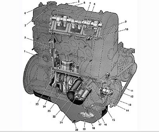
Lubrication system: 1 – channel in the cylinder block for supplying oil to the oil line of the cylinder head; 2 – channel in the cylinder head; 3 – branch pipe for removing crankcase gases into the air filter housing; 4 – oil filler cap; 5 – exhaust hose branch; 6 – branch pipe for removing crankcase gases into the carburetor's throttle space; 7 – oil line in the cylinder head; 8 – camshaft; 9 – oil supply channel to the camshaft bearing; 10 – oil pressure warning light sensor; 11 – pressure reducing valve; 12 – oil supply channel from the filter to the main oil line; 13 – oil pump drive gear; 14 – driven gear of the oil pump; 15 – oil supply channel from the pump to the filter; 16 – anti-drain valve; 17 – cardboard filter element; 18 – oil pan; 19 – oil receiver; 20 – drain plug; 21 – bypass valve; 22 – oil filter; 23 – oil supply channel from the crankshaft main bearing to the connecting rod; 24 – oil supply channel to the crankshaft main bearing; 25 – main oil line
The lubrication system is combined: splash and pressure. The system consists of an oil sump 18 (Fig. 4.5), a gear oil pump with an oil receiver, a full-flow oil filter, an oil pressure sensor 10 and oil valves. The main and connecting rod bearings, as well as the camshaft supports 8, are lubricated under pressure. By splashing, oil is supplied to the cylinder walls and then to the piston pins and rings, as well as to the camshaft cams, valve tappets and to the rods of the intake and exhaust valves. The oil pump is of the gear type, with a driven 14 and a driving 13 internal gear. The pressure created by the pump is regulated by a pressure reducing valve 11. The oil receiver 19 is bolted to the cover of the second main bearing and the pump body. Oil filter 22 – full-flow, non-separable, with bypass 21 and anti-drain valves, with cardboard filter element 17.