




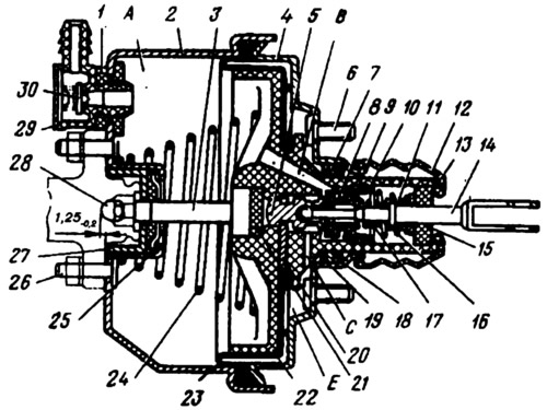
Fig. 193. Vacuum amplifier:
1 - tip mounting flange; 2 - amplifier body; 3 - rod; 4 - lid; 5 - piston; 6 - amplifier mounting bolt; 7 - distance ring; 8 - valve spring support cup; 9 - valve; 10 - valve support cup; 11 - return spring support cup; 12 - protective cap; 13 - protective cap holder; 14 - pusher; 15 - air filter; 16 - valve return spring; 17 - valve spring; 18 - housing cover seal; 19 - retaining ring; 20 - thrust plate; 21 - buffer; 22 - valve body; 23 - diaphragm; 24 - valve body return spring; 25 - rod seal; 26 - master cylinder mounting bolt; 27 - rod seal collar; 28 - adjusting bolt; 29 - hose tip; 30 - valve; A - vacuum cavity; B - a channel connecting the vacuum cavity with the internal cavity of the valve; C - a channel connecting the internal cavity of the valve with the atmospheric cavity; E - atmospheric cavity.
Repair of the vacuum booster is carried out at specialized enterprises equipped with special stands for their disassembly and leak testing after assembly. Therefore, operations for disassembly, assembly and repair of the vacuum booster are not given. If the operational malfunctions specified below occur, due to loss of operability of the vacuum booster, replace it, except for cases when its complete disassembly is not required, for example, when replacing the air filter and protective cap or putting grease into the seal of the booster housing.