
The working brake system consists of front and rear wheel brakes and hydraulic drive to them. One circuit of the hydraulic drive provides the action of the brake mechanisms of the front wheels, the other - the brake mechanisms of the rear wheels. The independent separate drive of the brake mechanisms of the front and rear wheels significantly increases the safety of the car.
The hydraulic drive includes a vacuum booster 3 (pic. 192) and pressure regulator 19 rear brakes. The first one increases the reliability of the brake system by reducing the effort on the brake pedal and creates comfort when driving a car, and the pressure regulator reduces the likelihood of rear wheel skidding during braking. The automatic device for adjusting the gap in the rear brake mechanism is located in the wheel cylinder.
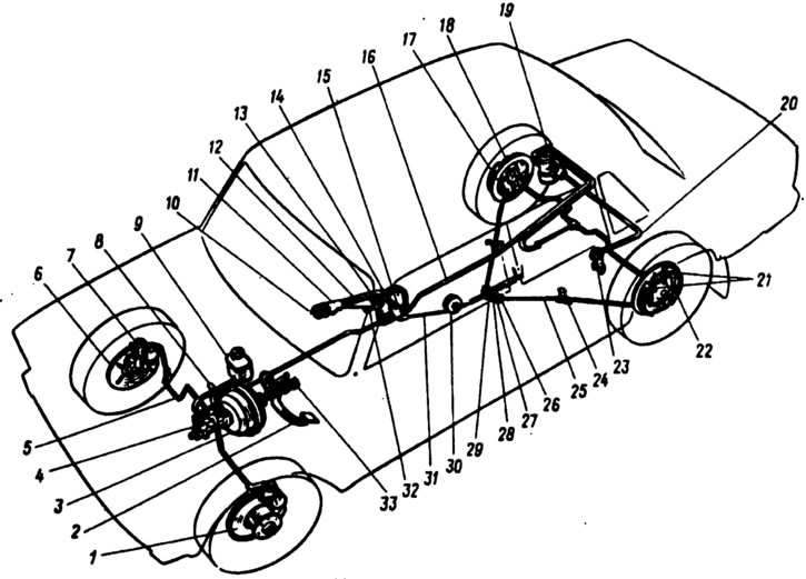
Pic. 192. Scheme of brake systems:
1 - brake disc; 2 - brake pedal; 3 - vacuum amplifier; 4 - the main cylinder of the hydraulic drive of the brakes; 5 - pipeline of the front brake drive circuit; 6 - protective cover of the front brake; 7 - front brake caliper; 8 - vacuum pipeline; 9 - tank of the main cylinder; 10 - button of the parking brake drive lever; 11 - parking brake drive lever; 12 - lever latch rod; 13 - lever latch; 14 - parking brake lever bracket; 15 - return lever; 16 - pipeline of the rear brake drive circuit; 17 - flange of the rear tip of the cable sheath; 18 - rear brake wheel cylinder; 19 - rear brake pressure regulator; 20 - pressure regulator drive lever; 21 - block of the brake mechanism; 22 - lever for manual drive of the pads; 23 - the thrust of the regulator drive lever is pressed; 24 - bracket attached to the front tip of the cable sheath; 25 - rear cable; 26 - locknut; 27 - adjusting nut; 28 - bushing; 29 - rear cable guide; 30 - guide roller; 31 - front cable; 32 - emphasis of the switch of a control lamp of a parking brake; 33 - stoplight switch.