
English Русский
Български
Беларускі
Український
Српски
Hrvatski
Română
Polski
Slovenský
Magyar
| Articles | Contacts | Sitemap |   
Repair and maintenance Lada Repair and maintenance Mazda Repair and maintenance Mitsubishi Repair and maintenance Toyota Repair and maintenance Land Rover Repair and maintenance Hyundai Repair and maintenance Nissan
VAZbook.ru


Main     1111   2101   2105   2106   2107   2109   2110   2115   2121  
VAZ-2104 (1984-2012) VAZ-2105 (1979-2010) VAZ-21051 (1979-2010)
  • Main
  • «Zhiguli»
  • VAZ-2105
  • Chassis
  • Brake system
  • The structure and operating principle of the master brake cylinder

The structure and operating principle of the master brake cylinder (VAZ-2105)

            0

The main brake cylinder is attached to the vacuum booster with two studs. It is unified on all models. But depending on the relative position of the main cylinder and its reservoir on the car, straight or angular fittings are used for the hoses connecting the main cylinder and reservoir.

Pistons 3 and 4 (Fig. 194) actuate different circuits. Both pistons take their initial position under the action of springs 7. The movement of the pistons under the action of the springs is limited by screws 6. The tightness of the pistons in the cylinder is ensured by four sealing rings 5. The cylinder body 2 is closed at the front by plug 1. In the initial position of the pistons, the spacer rings 9 rest against screws 6. In this case, the sealing rings 5 move away from the end surface of the piston grooves and through the resulting gaps B the working cavities of the cylinder are filled with liquid from the tank. The spacer ring 9 stops pressing on the sealing ring 5, and it, pressed under the action of spring 8 to the end of the piston groove, separates the cavity of the tank from the cavity of the cylinder. This ends the free travel of the piston, which on the brake pedal is 3-5 mm. With further movement of piston 4, the pressure in the cavity of the drive of the front wheel brake mechanisms increases and under its action, piston 3 of the drive of another circuit moves. With serviceable circuits, the pressure in both working cavities of the cylinder will increase equally.
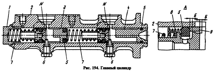
Pistons 3 and 4 (Fig. 194) actuate different circuits. Both pistons take their initial position…


The text is copied from the online portal (VazBook)


This article is available at russian, bulgarian, belarusian, ukrainian, serbian, croatian, romanian, polish, slovak, hungarian
The text was reviewed by the specialist: Grigory Vologodtsev

Share with friends:

Previous articles
VAZ-2105: Brake system
Next articles

Measuring the protrusion of the vacuum booster rod
Removal and installation the vacuum booster
The structure and operating principle of a vacuum booster
The structure and operation of the braking system
Checking and repairing the master brake cylinder
Brake pedal assembly device
Checking and repairing the brake pedal assembly
Rear brake pressure regulator device
Repair of the rear brake pressure regulator

More articles from other manuals on VAZ cars:
➠ The structure and operating principle of the master brake… VAZ-2101 (1970-1983)
➠ Removal and installation the master brake cylinder VAZ-11113 (1996-2003)
➠ Master Brake Cylinder — Removal and Installation VAZ-2106 (1976-2006)
➠ Master Brake Cylinder — Removal and Installation VAZ-2107 (1982-2012)
➠ Brake master cylinder VAZ-2109 (1984-1997)
Link in different formats to this page


Visitor comments

No comments yet


How much will 21 + 25 ?


VAZ-2104 (1984-2012) 
  • General information
  • Operation and maintenance
  • Power unit
  • Engine repair
  • Fuel system (carburetor)
  • Fuel system (injector)
  • Control system
  • Cooling system
  • Exhaust system
  • Transmission
  • Clutch
  • Car gearbox
  • Cardan gear
  • Rear axle
  • Chassis
  • Front suspension
  • Rear suspension
  • Wheels and tires
  • Steering
  • Brake system
  • Body
  • Exterior
  • Interior
  • Doors and glass
  • Ventilation and heating
  • Electrical equipment
  • Equipment and devices
  • Headlights and lighting
  • Engine electrics
  • Electrical circuits


VAZ-2105 (1979-2010) 
  • General information
  • Vehicle description
  • Vehicle device
  • Vehicle operation
  • Maintenance
  • Power unit
  • Engine repair
  • Cooling and lubrication system
  • Supply system
  • Transmission
  • Clutch
  • Car gearbox
  • Cardan gear
  • Rear axle
  • Chassis
  • Suspension and shock absorbers
  • Steering
  • Brake system
  • Body
  • Body elements
  • Electrical equipment
  • Engine electrics
  • Equipment and devices


VAZ-21051 (1979-2010) 
  • General information
  • Introduction to guide
  • User manual
  • Troubleshooting
  • Power unit
  • Engine repair
  • Engine repair VAZ-2103
  • Cooling system
  • Lubrication system
  • Power and exhaust system
  • Fuel injection
  • Transmission
  • Clutch
  • Car gearbox
  • Cardan gear
  • Rear axle
  • Chassis
  • Suspension and shock absorbers
  • Steering
  • Brake system
  • Body
  • Exterior
  • Interior
  • Doors and windows
  • Electrical equipment
  • Equipment and devices
  • Engine electrics
  • Ignition system
  • Electrical circuits


VAZbook.ru © 2017 · Mobile version · Contact with administration · Sitemap: EN BG BY UA RS HR RO PL SK HU · Site search · News and articles VAZ-1111 · VAZ-11113 · VAZ-2101 · VAZ-21011 · VAZ-2104 · VAZ-2105 · VAZ-21051 · VAZ-2106 · VAZ-21061 · VAZ-2107 · VAZ-21099 · VAZ-2109 · VAZ-2108 · VAZ-2110 · VAZ-2112 · VAZ-2114 · VAZ-2115 · VAZ-2121 · VAZ-21213 · VAZ-21214 ·
The site stores technical data using cookies to improve the service.