




Removal and disassembly
To remove the pendulum arm bracket, disconnect the pendulum arm from the ball joints of the middle and right side rods, having first unbolted the cotter pins and unscrewed the nuts and removed the ball joints from the arm sockets using the A.47052 puller. Then unscrew the bracket mounting bolts to the side member and remove it.
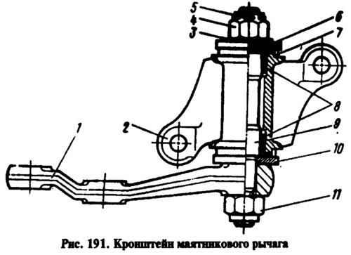
To disassemble, secure bracket 2 (Fig. 191) in a vice, remove cotter pin 5 and unscrew nut 4, then remove washers 3 and 6, pendulum arm 1 assembled with axle 9, washer 10 and self-locking nut 11, then remove seals 7 and press out bushings 8.
Examination
After disassembling, check the condition of the pendulum arm axle bushings and its axle. If there is ovality or damage, replace them. In addition, check whether the pendulum arm has deformations, otherwise, replace it as well.
(The material is posted on the online resource: vazbook.ru)
Assembly and installation
Before assembly, lubricate the pendulum lever axle bushings and fill the space between them with Litol-24 grease. The order of assembly of the pendulum lever bracket is the reverse of disassembly. In this case, if axle 9 was replaced, tighten the self-locking nut 11 of the lever mount with a torque wrench. Install washer 6 with the protrusions facing up. After tightening nut 4, the lever in the horizontal position should not rotate under its own weight. It should rotate under a force of 1-2 kgf applied to its end. If nut 4 is overtightened, unscrew it, lift washer 6 and tighten it again.
After this, secure the bracket to the body side member with bolts, self-locking nuts and flat washers and connect the ball joints of the rods to the pendulum arm.