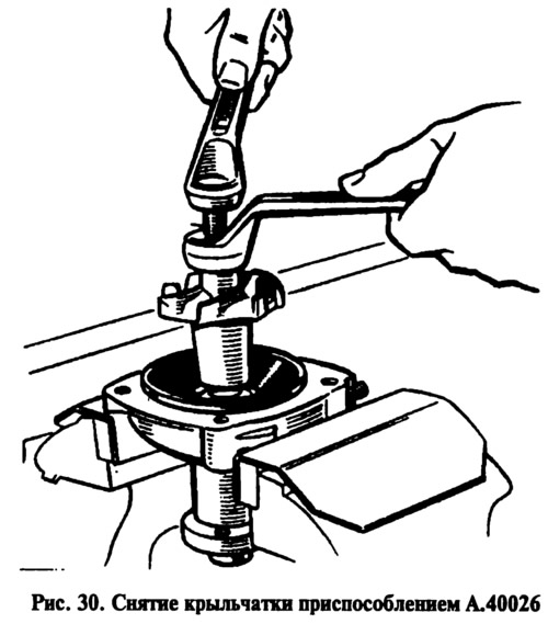
After unscrewing the locking screw 6 (see fig. 28), remove bearing 7 with the shaft and remove seal 11 from cover using a standard mandrel.
Assemble the pump in the reverse order. Do not skew it when installing it in the gland cover. Press in the bearing with the shaft so that the locking screw socket matches the hole in the pump cover. After tightening the bearing locking screw, calk the contours of the screw to prevent it from loosening.
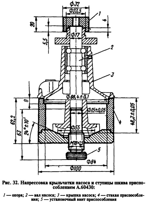
Using the A.60430 tool (Fig. 32), press the pulley hub onto the shaft, maintaining the dimension of (84.4±0.1) mm (see fig. 28), as well as the impeller, providing a size of 0.9-1.3 mm.
[View the original on the internet resource: VazBook.ru]