




The lubrication system includes: oil pump 1 (Fig. 33); suction pipe with filter mesh attached to the pump body; full flow oil filter mounted on the left side of the engine; filler neck with lid 19; oil level indicator in the crankcase; oil pressure sensor 23, connected to the control lamp.
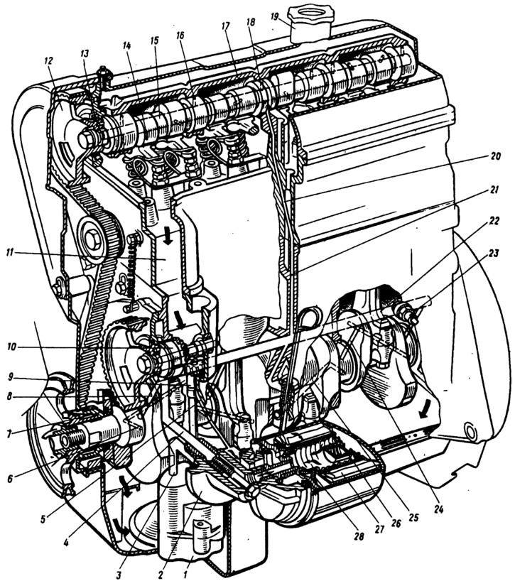
Fig. 33. Lubrication system:
1 - oil pump; 2 - oil filter bracket; 3 - oil supply channel from the pump to the filter; 4 - horizontal channel in the cylinder block for supplying oil from the filter to the oil line: 3 - channel in the cylinder block for supplying oil to the gear drive of the oil pump and ignition distributor; 6 - channel in the crankshaft journal; 7 - front crankshaft oil seal; 8 - oil supply channel from the oil line to the main bearing and to the auxiliary drive shaft; 9 - bushing of gear of drive of oil pump and ignition distributor; 10 - auxiliary drive shaft; 11 - channel for draining oil into the engine crankcase; 12 - camshaft pulley; 13 - camshaft oil seal; 4 - channel in the camshaft cam; 15 - main channel in the camshaft; 16 - channel in the bearing journal of the camshaft; 17 - camshaft bearing housing; 18 - annular groove on the middle support neck; 19 - oil filler cap; 20 - inclined channel in the cylinder head for supplying oil to the valve timing mechanism; 21 - vertical channel in the cylinder block; 22 - main oil channel; 23 - Oil pressure warning light sensor; 24 - oil supply channel to the main bearing; 25 - oil supply channel from the main bearing to the connecting rod; 26 - oil filter bypass valve; 27 - paper filter element of the oil filter; 28 - anti-drain valve.
Oil pump
The gear-type oil pump (Fig. 34) is installed inside the crankcase and is secured to the cylinder block with two bolts. The drive gear 8 is fixedly secured to the shaft 10 and is supplied as spare parts complete with the shaft. The driven gear 6 rotates freely on the axis P, pressed into the pump housing 7. The oil intake pipe 2 with the filter mesh 1 and the built-in pressure-reducing valve 3, which is pressed by a spring against the pump cover 5, is secured to the pump housing. The valve actuation pressure is provided by the spring 4 of the corresponding elasticity.
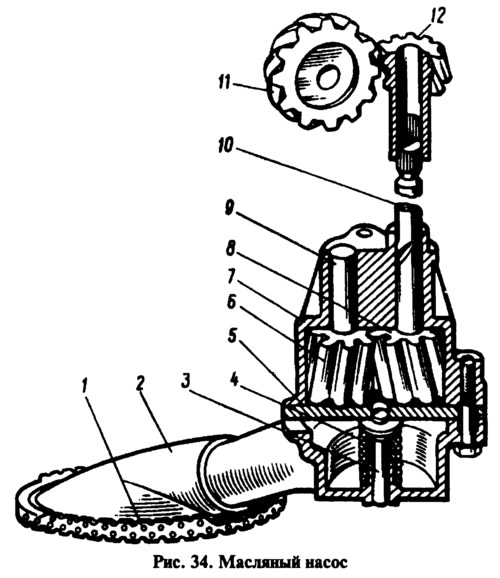
The oil pump is driven from the timing belt to the auxiliary drive shaft, then through a pair of spiral gears 11 and 12 to the oil pump shaft 10. Gear 12 of the oil pump drive rotates in a metal-ceramic bushing pressed into the cylinder block. The splined hole of the gear receives the shafts of the oil pump and the ignition distributor.
The oil pump and its drive are installed from the 2101 engine. The exception is for 2105 engines, which have a timing belt transmission, which have 10 on the shaft (see fig. 33) the belt drive pulley is installed.
Oil filter
The oil filter is full-flow, non-separable. Until 1986, the engines were equipped with oil filter 2101 (shown in Fig. 33), which, due to its larger dimensions than the 2105 filter, was installed using bracket 2. Later, the 2105 filter was installed on all the engines described. Due to the smaller dimensions of the filter, it can be installed on all VAZ car engines.
Engine crankcase ventilation
Provides forced removal of gases and gasoline vapors from the crankcase.
Crankcase gases are sucked off through hose 9 (Fig. 35), put on the branch pipe of cover 10 of oil separator 11, into suction manifold 7, located under the air filter. From there gases can be sucked off in two ways: upwards into the space behind filter element 6 of the air filter and further through the carburetor into the engine intake pipe and through hose 5 into the valve device of the carburetor and further into the throttle space of the carburetor.
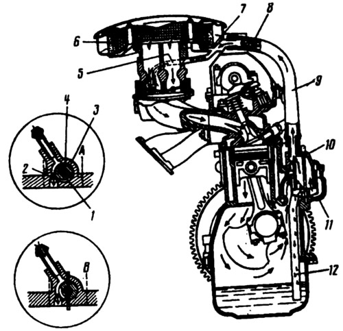
Fig. 35. Engine crankcase ventilation diagram:
A and B — operation of the carburetor spool valve at low (A) and high (B) crankshaft speed;
1 - spool groove; 2 - calibrated hole; 3 - valve; 4 - first chamber throttle valve axis; 5 - hose for removing gases into the throttle space of the carburetor; 6 - air filter element; 7 - suction manifold; 8 - flame arrester; 9 - gas suction hose; 10 - oil separator cover; 11 - oil separator; 12 - oil separator drain pipe.
The slide valve device regulates the gas suction mode at different engine crankshaft speeds. It consists of a slide valve 3 located on the axis 4 of the first chamber throttle valve and a calibrated hole 2 in the carburetor throttle valve body.
The original source is located on the website (vazbook)