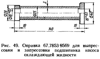
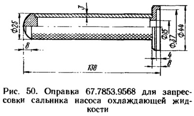
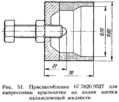
When assembling the pump using the mandrel 67.7853.9568 (figure 50) install the seal into the pump body without distortions. Using the mandrel 67.7853.9569 (see figure 49) press in the roller with the bearing so that the socket of the locking screw 1 (see figure 10) coincides with the hole in the pump body. Tighten the bearing lock screw and calk the contours of the socket to prevent the screw from loosening. Then, using the device 67.7820.9527 (figure 51) press on impeller 4 (see figure 10) and toothed pulley 9, maintaining the dimensions (52±0.5) mm and (39.8±0.1) mm indicated on figure 10. Before pressing the pulley, heat it up to 150-200°C. After the pulley has cooled, attach the pump to the impeller and check the reliability of the pulley connection on the shaft by applying a torque of 24.5 N·m to the pulley. The pulley should not turn.