




Contents: Cylinder block ↓ Cylinder head ↓ Pistons ↓ Piston pins ↓ Connecting rods ↓ Crankshaft ↓ Inserts ↓ Gas distribution mechanism ↓ Auxiliary unit drive ↓ Engine operation ↓
Open large image in new tab »
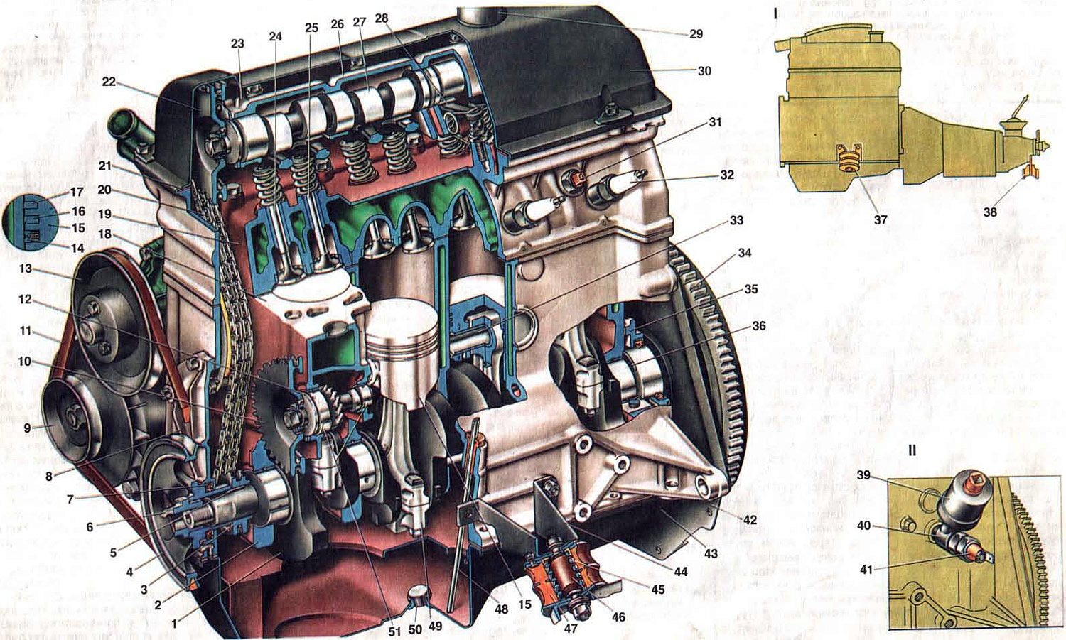
Fig. 3. Engine (longitudinal section).
1. Crankshaft; 2. First main bearing cap; 3. Crankshaft sprocket; 4. Crankshaft pulley; 5. Crankshaft pulley and sprocket key; 6. Ratchet; 7. Front crankshaft oil seal; 8. Timing mechanism drive cover; 9. Generator pulley; 10. Sprocket for driving the oil pump, fuel pump and ignition distributor; 11. Coolant pump and generator drive belt; 12. Drive shaft of oil pump, fuel pump and ignition distributor; 13. Coolant water pump pulley; 14. Oil scraper ring; 15. Piston; 16. Lower compression ring; 17. Upper compression ring; 18. Cylinder block; 19. Cylinder head; 20. Timing chain; 21. Cylinder head cover gasket; 22. Camshaft sprocket; 23. Mounting protrusion on the camshaft bearing housing; 24. Exhaust valve. 25. Inlet valve; 26. Camshaft bearing housing; 27. Camshaft; 28. Valve drive lever; 29. Oil filler neck. 30 Cylinder head cover; 31. Coolant temperature gauge sensor; 32. Spark plug; 33. Piston pin; 34. Flywheel; 35. Crankshaft rear oil seal holder; 36. Crankshaft thrust half ring; 37. Front engine mount; 38. Rear engine mount; 39. Oil pressure indicator sensor; 40. Nipple; 41. Oil pressure warning light sensor; 42. Front clutch housing cover; 43. Oil pan; 44. Front support bracket; 45. Front support spring; 46. Front support cushion buffer; 47. Front support rubber cushion; 48. Oil level indicator; 49. Connecting rod with cover assembly; 50. Oil pan drain plug; 51. Bushings of the drive shaft of the oil pump, fuel pump and ignition distributor.
1. Crankshaft; 2. First main bearing cap; 3. Crankshaft sprocket; 4. Crankshaft pulley; 5. Crankshaft pulley and sprocket key; 6. Ratchet; 7. Front crankshaft oil seal; 8. Timing mechanism drive cover; 9. Generator pulley; 10. Sprocket for driving the oil pump, fuel pump and ignition distributor; 11. Coolant pump and generator drive belt; 12. Drive shaft of oil pump, fuel pump and ignition distributor; 13. Coolant water pump pulley; 14. Oil scraper ring; 15. Piston; 16. Lower compression ring; 17. Upper compression ring; 18. Cylinder block; 19. Cylinder head; 20. Timing chain; 21. Cylinder head cover gasket; 22. Camshaft sprocket; 23. Mounting protrusion on the camshaft bearing housing; 24. Exhaust valve. 25. Inlet valve; 26. Camshaft bearing housing; 27. Camshaft; 28. Valve drive lever; 29. Oil filler neck. 30 Cylinder head cover; 31. Coolant temperature gauge sensor; 32. Spark plug; 33. Piston pin; 34. Flywheel; 35. Crankshaft rear oil seal holder; 36. Crankshaft thrust half ring; 37. Front engine mount; 38. Rear engine mount; 39. Oil pressure indicator sensor; 40. Nipple; 41. Oil pressure warning light sensor; 42. Front clutch housing cover; 43. Oil pan; 44. Front support bracket; 45. Front support spring; 46. Front support cushion buffer; 47. Front support rubber cushion; 48. Oil level indicator; 49. Connecting rod with cover assembly; 50. Oil pan drain plug; 51. Bushings of the drive shaft of the oil pump, fuel pump and ignition distributor.
Open large image in new tab »
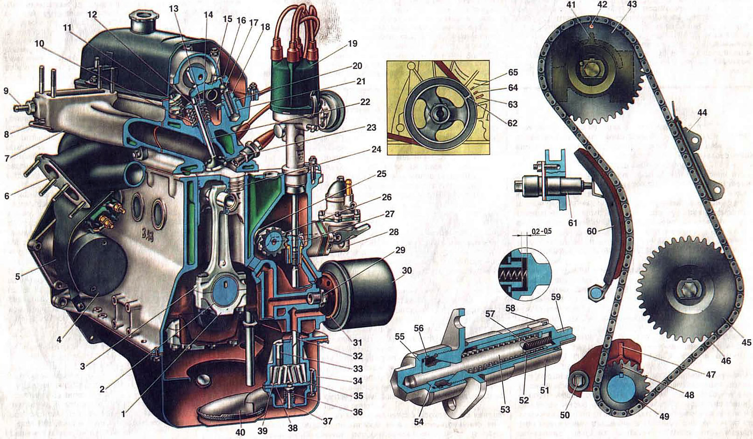
Fig. 4. Engine (cross section).
1. Connecting rod cap; 2. Connecting rod bearings; 3. Connecting rod; 4. Starter; 5. Starter heat shield; 6. Exhaust manifold; 7. Intake pipe; 8- Inlet pipe drain tube; 9. Coolant drain pipe fitting; 10. Outer valve spring; 11. Inner valve spring; 12. Valve cracker; 13. Spring plate; 14. Oil deflector cap; 15. Valve drive lever; 16. Valve drive lever spring; 17. Valve adjusting bolt; 18. Adjusting bolt lock nut; 19. Ignition distributor; 20. Valve lever spring retaining plate; 21. Adjusting bolt bushing; 22. Valve guide bushing; 23. Valve seat; 24. Piston; 25. Eccentric for fuel pump drive; 26. Auxiliary drive shaft; 27. Gear for driving the oil pump and ignition distributor; 28. Fuel pump; 29. Oil filter mounting nipple; 30. Oil filter: 31. Gasket; 32. Oil pump roller; 33. Oil pump driven gear shaft; 34. Oil pump housing; 35. Oil pump drive gear; 36. Pressure reducing valve spring; 37. Oil pump pressure reducing valve; 38. Oil pump cover; 39. Oil pump driven gear; 40. Oil pump inlet pipe; 41. Mounting protrusion on the camshaft bearing housing; 42. Timing mark on the camshaft sprocket; 43. Camshaft sprocket; 44. Chain tensioner; 45. Auxiliary drive sprocket; 46. Camshaft drive chain; 47. Timing mark on the cylinder block; 48. Timing mark on the crankshaft sprocket; 49. Crankshaft sprocket; 50. Limiting finger; 51. Chain tensioner housing; 52. Chain tensioner spring; 53. Tensioner rod; 54. Rod clamping cracker; 55. Cap nut; 56. Spring ring; 57. Plunger spring; 58. Plunger retaining ring; 59. Tensioner plunger; 60. Tensioner shoe; 61. Tensioner; 62. TDC mark on the crankshaft pulley; 63. 0° ignition advance mark; 64. 5° ignition advance mark; 65. 10° ignition advance mark.
1. Connecting rod cap; 2. Connecting rod bearings; 3. Connecting rod; 4. Starter; 5. Starter heat shield; 6. Exhaust manifold; 7. Intake pipe; 8- Inlet pipe drain tube; 9. Coolant drain pipe fitting; 10. Outer valve spring; 11. Inner valve spring; 12. Valve cracker; 13. Spring plate; 14. Oil deflector cap; 15. Valve drive lever; 16. Valve drive lever spring; 17. Valve adjusting bolt; 18. Adjusting bolt lock nut; 19. Ignition distributor; 20. Valve lever spring retaining plate; 21. Adjusting bolt bushing; 22. Valve guide bushing; 23. Valve seat; 24. Piston; 25. Eccentric for fuel pump drive; 26. Auxiliary drive shaft; 27. Gear for driving the oil pump and ignition distributor; 28. Fuel pump; 29. Oil filter mounting nipple; 30. Oil filter: 31. Gasket; 32. Oil pump roller; 33. Oil pump driven gear shaft; 34. Oil pump housing; 35. Oil pump drive gear; 36. Pressure reducing valve spring; 37. Oil pump pressure reducing valve; 38. Oil pump cover; 39. Oil pump driven gear; 40. Oil pump inlet pipe; 41. Mounting protrusion on the camshaft bearing housing; 42. Timing mark on the camshaft sprocket; 43. Camshaft sprocket; 44. Chain tensioner; 45. Auxiliary drive sprocket; 46. Camshaft drive chain; 47. Timing mark on the cylinder block; 48. Timing mark on the crankshaft sprocket; 49. Crankshaft sprocket; 50. Limiting finger; 51. Chain tensioner housing; 52. Chain tensioner spring; 53. Tensioner rod; 54. Rod clamping cracker; 55. Cap nut; 56. Spring ring; 57. Plunger spring; 58. Plunger retaining ring; 59. Tensioner plunger; 60. Tensioner shoe; 61. Tensioner; 62. TDC mark on the crankshaft pulley; 63. 0° ignition advance mark; 64. 5° ignition advance mark; 65. 10° ignition advance mark.
The cars are equipped with engines of the same design, but with different cylinder volumes. They differ mainly in the dimensions of the cylinder block, pistons, crankshaft and chain drive components.
Cylinder block
Cylinder block 18 is cast from special cast iron. The cylinders of the block are divided by diameter into five classes, designated by the letters A, B, C, D, E, by 0.01 mm. The cylinder class is indicated on the lower plane of the block opposite each cylinder. The cylinder and the piston mating with it must be of the same class to ensure a clearance between the piston and the cylinder of 0.05-0.07 mm. The cylinder diameters of each class are as follows, mm:
| Class | Cylinder diameter of engines 2101, 2103 | Cylinder diameter of engines 21011, 2106 |
| A | 76,000-76,010 | 79,000-79010 |
| IN | 76,010-76,020 | 79,010-79,020 |
| WITH | 76,020-76,030 | 79,020-79,030 |
| D | 76,030-76,040 | 79,030-79,040 |
| E | 76,040-76,050 | 79,040-79,050 |
In the lower part of the cylinder block there are five supports of the main bearings of the crankshaft with thin-walled steel-aluminum liners. The holes for the crankshaft bearings in the cylinder block are machined together with the covers 2. Therefore, the bearing covers are not interchangeable, and for distinction on their outer surface there are marks.
The rear support has sockets for installing thrust half rings 36, which hold the crankshaft from axial movements. A steel-aluminum half ring is installed at the front, and a metal-ceramic half ring is installed at the rear (yellow color), impregnated with oil. The value of the axial clearance of the crankshaft during engine assembly is provided within the range of 0.06-0.26 mm. If during operation the clearance exceeds the maximum permissible (0.35 mm), it is necessary to replace the thrust half rings with new ones or repair ones, increased by 0.127 mm. The grooves located on one side of the half rings must face the thrust surfaces of the crankshaft.
In the front part of the cylinder block there is a cavity for the valve timing drive, closed by cover 8. At the rear side, a holder 35 of the rear oil seal is attached to the cylinder block. Self-tightening oil seals are installed in cover 8 and holder 35. In the left part of the block, a shaft 12 of the auxiliary unit drive is installed. Steel-aluminum bushings 51 are pressed into the holes for the shaft bearings.
Cylinder head
The cylinder head 19 is common for four cylinders, cast from aluminum alloy. Cast iron seats and valve guides are pressed into the head. Spiral grooves for lubrication are cut in the holes of the guides. Metal-rubber oil-deflecting caps are used to reduce oil penetration into the combustion chamber through the gaps between the sleeve and the valve stem.
The cylinder head is attached to the cylinder block with eleven bolts. Between the head and the cylinder block there is a gasket made of asbestos material on a metal frame and impregnated with graphite.
Pistons
Pistons 15 are made of aluminum alloy and coated with a layer of tin to improve running-in. The piston skirt is oval in cross-section and conical in height. In addition, steel thermoregulating plates are poured into the piston bosses. All this is done to compensate for uneven thermal deformation of the piston when heated. There are holes in the piston bosses for the passage of oil to the piston pin.
The hole for the piston pin is offset from the axis of symmetry by 2 mm to the right side of the engine to reduce the knock of the piston when passing through the TDC. Therefore, there is a mark "P" near the hole for the piston pin, which should face the front of the engine during assembly.
Pistons, like cylinders, are sorted by outer diameter into five classes through 0.01 mm, and by diameter of the hole under the piston pin - into three categories through 0.001 mm, designated by numbers 1, 2, 3. The piston class (letter) and the category of the hole under the piston pin (number) are stamped on the piston bottom. Pistons by weight in the same engine must be selected with the maximum permissible deviation (2.5 g).
Piston pins
Piston pins 14, 16 and 17 are made of cast iron. The outer surface of the upper compression ring 17 is chromed to increase wear resistance and has a barrel-shaped generatrix to improve running-in. The lower compression ring 16 is of the scraper type (with groove on outer surface), phosphated.
The ring must be installed with the groove facing down. Oil scraper ring 14 has slots for the oil removed from the cylinder and an internal coil spring (expander).
Connecting rods
Connecting rods 49 - steel, forged, with a split lower head in which the connecting rod bearing liners are installed. The connecting rod is machined together with the cover, therefore, when assembling, the numbers on the connecting rod and cover must be the same.
Crankshaft
Crankshaft 1 is a five-bearing, cast iron crankshaft. The journals of the shaft are hardened by high-frequency currents to a depth of 2-3 mm. At the rear end of the crankshaft, a seat is made for the front bearing of the primary shaft of the gearbox, along the outer diameter of which the flywheel 31 is centered. The flywheel is installed on the crankshaft so that the mark (cone-shaped hole near the toothed rim of the flywheel) and the axis of the connecting rod journal of the first cylinder were in the same plane and one from the axis of the crankshaft.
Inserts
The main and connecting rod bearing shells are thin-walled, steel-aluminum. All connecting rod shells are identical and interchangeable. The upper shells of the 1st, 2nd, 4th and 5th main bearings are identical, with a groove on the inner surface, and the lower ones are without a groove. The shells of the 3rd main bearing differ from the others in their greater width and the absence of a groove on the inner surface.
Gas distribution mechanism
The valve timing mechanism ensures that the engine cylinders are filled with a combustible mixture and exhaust gases are released in accordance with the cylinder operating order and valve timing phases adopted for the engine. The mechanism parts include: the camshaft, valves and guide bushings, springs with fastening parts, and valve drive levers.
The camshaft, which controls the opening and closing of the valves, is cast iron. The rubbing surfaces of the cams are subjected to bleaching. This process consists of electric arc melting of the surfaces, as a result of which a layer of so-called "white" cast iron is formed, which has high hardness. The shaft rotates on five supports in a special housing 26 (see fig. 3), and is held from axial movements by a thrust flange placed in the groove of the front support journal of the shaft.
Valves (inlet and outlet) are located in the cylinder head at an angle in one row. The head of the inlet valve has a larger diameter for better filling of the cylinder, and the working chamfer of the exhaust valve, which operates at high temperatures in an aggressive environment of exhaust gases, has a surfacing made of heat-resistant alloy. Springs 10 and 11 (Fig. 4) press the valve to the seat and do not allow it to come off the drive lever. The upper support plate 13 of the springs is held on the valve stem by two crackers 12, which have the shape of a truncated cone when folded.
Levers 15 transmit the force from the camshaft cam to the valve. One end of the lever rests on the spherical head of the adjusting bolt 17, and the other on the end of the valve. The adjusting bolt is screwed into the bushing 21 and is locked with a lock nut 18.
Auxiliary unit drive
The auxiliary units of the engine and the valve timing mechanism are driven from the crankshaft by means of a chain transmission. It consists of a double-row sleeve-roller chain 46, a driving sprocket 49 on the crankshaft, a driven sprocket 43 of the camshaft, a chain damper 44 and a tensioner 61 with a shoe 60. The tensioner shoe and the chain damper have a steel frame with a vulcanized rubber layer.
When the locking nut 55 is loosened, the chain is tensioned by the shoe 60, which is acted upon by the springs 52 and 57 through the plunger 59. The tensioner shoe rotates around the fastening bolt. After tightening the nut 55, the rod 53 is clamped by the collets of the cracker 54, as a result of which the spring 52 of the chain tensioner is blocked. When the engine is running, only the internal spring 57 acts on the plunger 59, which ensures compensation for chain vibrations due to the gap of 0.2-0.5 mm in the tensioner mechanism. The chain damper 44 dampens vibrations of the leading branch of the chain. When the engine is running, the chain is stretched. It is considered to be operational if the tensioner ensures its tension, i.e. if the chain has stretched no more than 4 mm.
The shaft 26 of the drive of the oil pump, ignition distributor and fuel pump is installed along the engine and has two support journals, a helical gear and an eccentric 25, which drives the fuel pump through a pusher. The helical gear of the shaft 26 is in engagement with the gear 27, which drives the ignition distributor and the oil pump. The gear 27 rotates in a metal-ceramic bushing pressed into the cylinder block. The gear has a hole with splines, into which the splined ends of the shafts of the ignition distributor and the oil pump enter.
Engine operation
During one working cycle, four strokes occur in the engine cylinder - intake of the hot mixture, compression, power stroke and exhaust of the exhaust gases. These strokes are carried out in two revolutions of the crankshaft, i.e. each stroke occurs in half a revolution (180°) of the crankshaft.
The intake valve begins to open 12° before the piston approaches the top dead center (TDC). This is necessary so that the valve is fully open when the piston goes down. The valve closes 40° after the piston passes the bottom dead center (BDC). Due to the inertial pressure of the stream of the sucked-in combustible mixture, it continues to enter the cylinder when the piston has already begun to move up, and thus ensures better filling of the cylinder.
The exhaust valve begins to open 42° before BDC. At this point, the pressure in the cylinder is still quite high, and gases begin to flow out of the cylinder intensively. The valve closes 10° after the piston passes TDC.
There is a moment (22° of crankshaft rotation near TDC) when both valves are open simultaneously - intake and exhaust. This position is called valve overlap. Due to the short time interval, valve overlap does not lead to the penetration of exhaust gases into the intake manifold, but on the contrary, the inertia of the exhaust gas flow causes the suction of the combustible mixture into the cylinder and improves its filling.
To ensure that the valve opening and closing times are coordinated with the crankshaft rotation angles (i.e. to ensure the correct installation of the valve timing), there are marks 48 and 42 on the crankshaft and camshaft sprockets, as well as 47 on the cylinder block and 41 (protrusion) on the camshaft bearing housing. If the valve timing is set correctly, then when the piston of the fourth cylinder is in TDC at the end of the compression stroke, mark 41 should coincide with mark 42, and mark 48 with mark 47. When the camshaft drive cavity is closed with a cover, the position of the crankshaft can be determined by the marks on the crankshaft pulley and the camshaft drive cover.
To ensure proper operation of the valve timing mechanism during thermal expansion of parts on a running engine, the clearances between the cams and valve drive levers are set to 0.15 mm on a cold engine. If the clearances are larger, the valves will open late and close early. If there is no clearance, the valves will remain slightly open on a running engine. As a result, the service life of the valves and seats will be sharply reduced, and engine power will drop.