




Open large image in new tab »
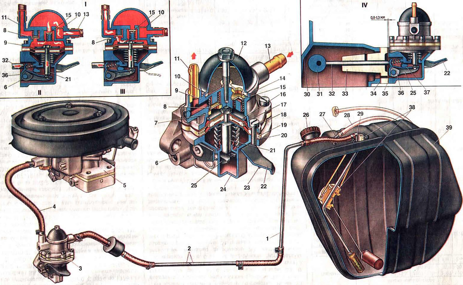
Fig. 7. Power supply system.
1. Rear fuel pipe; 2. Front fuel pipe; 3. Fuel pump; 4. Hose from the fuel pump to the carburetor; 5. Carburetor; 6. Axis of the mechanical fuel supply lever; 7. Discharge valve seat; 8. Discharge valve; 9. Upper pump body; 10. Filter; 11. Discharge pipe; 12. Pump cover; 13. Suction pipe; 14. Suction valve seat; 15. Suction valve; 16. Diaphragm plate; 17. Internal spacer gasket; 18. Upper diaphragms; 19. External spacer gasket; 20. Lower diaphragm; 21. Rod; 22. Manual fuel pump lever; 23. Lever spring; 24. Lower pump housing; 25. Balance beam; 26. Fuel tank cap; 27. Fuel tank air pipe; 28. Fuel tank vent hose; 29. Intake pipe; 30. Cylinder block; 31. Eccentric shaft of oil pump and ignition distributor drive; 32. Pusher; 33. Fuel pump heat-insulating spacer; 34. Laying the heat-insulating spacer; 35. Fuel pump gasket; 36. Pump mechanical drive lever; 37. Cam; 38. Fuel level indicator sensor; 39. Fuel tank; I. Fuel pump operation diagram; II. Fuel pump installation diagram.
1. Rear fuel pipe; 2. Front fuel pipe; 3. Fuel pump; 4. Hose from the fuel pump to the carburetor; 5. Carburetor; 6. Axis of the mechanical fuel supply lever; 7. Discharge valve seat; 8. Discharge valve; 9. Upper pump body; 10. Filter; 11. Discharge pipe; 12. Pump cover; 13. Suction pipe; 14. Suction valve seat; 15. Suction valve; 16. Diaphragm plate; 17. Internal spacer gasket; 18. Upper diaphragms; 19. External spacer gasket; 20. Lower diaphragm; 21. Rod; 22. Manual fuel pump lever; 23. Lever spring; 24. Lower pump housing; 25. Balance beam; 26. Fuel tank cap; 27. Fuel tank air pipe; 28. Fuel tank vent hose; 29. Intake pipe; 30. Cylinder block; 31. Eccentric shaft of oil pump and ignition distributor drive; 32. Pusher; 33. Fuel pump heat-insulating spacer; 34. Laying the heat-insulating spacer; 35. Fuel pump gasket; 36. Pump mechanical drive lever; 37. Cam; 38. Fuel level indicator sensor; 39. Fuel tank; I. Fuel pump operation diagram; II. Fuel pump installation diagram.
The fuel system includes devices for feeding fuel and air to the carburetor, preparing the combustible mixture and releasing exhaust gases. The fuel system consists of a fuel tank, fuel pump, air filter, carburetor, intake pipe, exhaust manifold, mufflers and pipelines. Fuel cleaning in the car is carried out by fuel filters installed on the intake pipe of the fuel level sensor in the tank, in the fuel pump and carburetor.
Fuel tank
Fuel tank 39 steel, welded from two halves. Steel sheets are lead-lined on the inside. The outside of the tank is painted with black enamel. Fuel tank capacity is 39 l, including a reserve of 4-6.5 l.
The tank is installed in the luggage compartment of the body on the right side of the vehicle on a rubber gasket and secured to the body with two clamps tightened with a bolt. The filler neck of the tank is brought out into a niche in the right rear wing and is closed with a blind plug 26 on a thread. To access the plug, it is necessary to press on the front end of the cover on the wing, which closes the niche.
For ventilation and access to atmospheric air, the fuel tank has a hose 28, the other end of which is led into the niche of the filler neck. Fuel that gets into the loop of the ventilation hose when the car is moving on an uneven road forms a liquid seal that prevents gasoline from evaporating from the tank.
The fuel level sensor 38 is mounted on top of the tank, complete with a branch pipe and a receiving pipe 29, equipped with a fuel mesh filter. The tank has a drain plug, for access to which there is a hole in the body floor, closed with a plug. Since 1985, drain plugs on fuel tanks have not been installed on cars.
Fuel lines
Fuel lines 1 and 2 are made of galvanized or lead-coated steel tubes. The fuel lines are connected to each other, to the tank, to the fuel pump, and also the fuel pump 3 to the carburetor 5, with rubber hoses in a fabric braid and are secured with clamps with a screw and a nut. On the body, the fuel lines are secured with plastic holders. The holes in the body for the passage of fuel lines are sealed with rubber plugs.
Fuel pump
Fuel pump - diaphragm type, mechanically driven; mounted on the left side of the cylinder block, secured on two studs through a heat-insulating spacer 33 and adjusting linings 34 and 35. Equipped with a lever 22 for manual fuel pumping. The pump output is at least 60 l/h at a pumping frequency of 2000 cycles per minute. The pressure developed by the pump is 20-30 kPa.
The fuel pump is driven by the eccentric 31 of the oil pump drive shaft and the ignition distributor via the pusher 32. The pump consists of the lower housing 24 with drive levers, the upper housing 9 with valves and pipes, the diaphragm unit and the cover 12.
The diaphragm unit has three diaphragms: two upper 18 - working for fuel supply, one lower 20 - safety, working in contact with crankcase oil and preventing fuel from entering the engine crankcase if the working diaphragms are damaged. Between the working and safety diaphragms, remote outer 19 and inner 17 gaskets are installed. The outer gasket has an opening for fuel to exit if the working diaphragms are damaged.
Diaphragms with plates and with internal spacer gasket 17 are installed on rod 21 and secured from above with a nut. The diaphragm unit is installed between the upper and lower pump housings. A compressed spring is installed under the diaphragm unit on the rod. Rod 21 is inserted with a T-shaped tailpiece into the slot of balancer 25. This design allows the diaphragm unit to be removed from the engine without disassembling it.
In the lower housing 24, on the axis 6, the lever 36 for mechanical fuel supply and the balancer 25 are installed. In the lower housing, also on the axis with the cam 37, the lever 22 for manual fuel pumping is installed, which, under the action of the spring 23, returns to its original position.
In the upper casing 9 of the pump, textolite hexagonal suction 15 and discharge 8 valves are installed. The valves are pressed by springs to brass seats 7 and 14. The cover 12 is fastened to the casing from above with a central bolt. A plastic mesh filter 10 is installed between the cover and the casing. In the upper casing 9 of the pump, suction 13 and discharge 11 pipes are pressed in.
When the engine is running, the eccentric 31 of the drive shaft acts on the lever 36 via the pusher 32 and turns the balancer 25, which pulls the pump diaphragms down by the rod 21. At the same time, the diaphragm spring is compressed even more, creating a vacuum, as a result of which the fuel fills the working cavity through the suction valve (cavity above the diaphragms). When the eccentric runs off the pusher, the lever 36, balancer 25 and rod with diaphragms are released. The diaphragms, under the action of the compressed spring, create fuel pressure in the working chamber, the suction valve 15 closes, and the fuel is fed through the discharge valve 8 into the float chamber of the carburetor.
At low fuel consumption the diaphragm stroke will be incomplete; in this case, the stroke of lever 36 will be partially idle.
When manually pumping fuel, press lever 22, cam 37 acts on balancer 25 and pulls back the rod with diaphragms. Fuel is sucked into the working cavity. When released, the lever and cam under the action of spring 23 return to their original position, and the diaphragms pump fuel into the carburetor float chamber.
When installing the fuel pump on the engine, adjusting linings 34 and 35 are selected in such a way that the minimum protrusion of the pusher 32 above the mating plane of the heat-insulating spacer 33 (taking into account the gasket between the spacer and the fuel pump) was 0.8-1.3 mm. The minimum protrusion of the pusher is set by slowly turning the engine crankshaft. Gaskets are made in three types and have a thickness of 0.30; 0.75 and 1.25 mm. A 0.30 mm thick gasket should always be placed between the heat-insulating spacer and the cylinder block.
[Original source is on the resource VazBook]