

Open large image in new tab »
Pic. 8. Carburetors.
1. The main fuel jet of the first chamber; 2. Screw for adjusting the fuel supply of the accelerator pump; 3. Bypass jet of the accelerator pump; 4. Accelerator pump drive cam; 5 Throttle valve return spring of the first chamber; 6. Accelerator pump drive lever; 7. Screw limiting the closing of the throttle valve of the 1st chamber; 8. Diaphragm accelerator pump; 9. Composition adjusting screw (quality) idling mixtures with restrictive sleeve: 10 Pipe for vacuum supply to the vacuum regulator of the ignition distributor; 11. Adjusting screw for the amount of idle mixture; 12. Idle fuel jet shut-off valve; 13. Carburetor body; 14 Trigger adjustment screw; 15. Diaphragm of the starting device; 16 Starter air jet; 17. Carburetor cover; 18. Air jet of the idle system; 19 Accelerator pump atomizer; 20. Main air jets; 21. Economizer emulsion jet (econostat); 22. Economizer fuel jet; 23. Economizer air jet; 24 Emulsion tube; 25. Float; 26 Needle valve; 27. Fuel filter; 28. Housing of the fuel jet of the transition system of the second chamber; 29. Pneumatic throttle valve of the second chamber - 30. Small diffuser of the mixing chamber; 31 Atomizer; 32. Air damper; 33. Lever axle air damper; 34 Telescopic air damper rod; 35. Launcher rail; 36. The body of the starting device. 37 Screw for fastening the air damper drive rod; 38. Three-arm lever; 39. Bracket return spring; 40 Crankcase exhaust pipe; 41, Arm return spring; 42 Throttle actuator lever; 43. Throttle valve axis of the first chamber; 44 Connecting rod for air and throttle actuators. 45. The lever that limits the opening of the throttle valve of the second chamber: 46. The linkage lever with the air damper; 47. The rod of the pneumatic throttle valve of the second chamber; 48. Lever connected to lever 49 through a spring; 49. Lever, rigidly fixed on the axis 43; 50. Screw for adjusting the closing of the throttle valve of the 2nd chamber. 51. Throttle valve of the second chamber; 52. Diaphragm of the pneumatic actuator of the throttle valve of the 2nd chamber; 53. Holes of the transition system of the second chamber; 54. Throttle body; 55. Fuel jet idling; 56. Shut-off valve needle; 57. Shut-off valve body; 58. Anchor of an electromagnet; 59. Winding of the coil of an electromagnet.
1. The main fuel jet of the first chamber; 2. Screw for adjusting the fuel supply of the accelerator pump; 3. Bypass jet of the accelerator pump; 4. Accelerator pump drive cam; 5 Throttle valve return spring of the first chamber; 6. Accelerator pump drive lever; 7. Screw limiting the closing of the throttle valve of the 1st chamber; 8. Diaphragm accelerator pump; 9. Composition adjusting screw (quality) idling mixtures with restrictive sleeve: 10 Pipe for vacuum supply to the vacuum regulator of the ignition distributor; 11. Adjusting screw for the amount of idle mixture; 12. Idle fuel jet shut-off valve; 13. Carburetor body; 14 Trigger adjustment screw; 15. Diaphragm of the starting device; 16 Starter air jet; 17. Carburetor cover; 18. Air jet of the idle system; 19 Accelerator pump atomizer; 20. Main air jets; 21. Economizer emulsion jet (econostat); 22. Economizer fuel jet; 23. Economizer air jet; 24 Emulsion tube; 25. Float; 26 Needle valve; 27. Fuel filter; 28. Housing of the fuel jet of the transition system of the second chamber; 29. Pneumatic throttle valve of the second chamber - 30. Small diffuser of the mixing chamber; 31 Atomizer; 32. Air damper; 33. Lever axle air damper; 34 Telescopic air damper rod; 35. Launcher rail; 36. The body of the starting device. 37 Screw for fastening the air damper drive rod; 38. Three-arm lever; 39. Bracket return spring; 40 Crankcase exhaust pipe; 41, Arm return spring; 42 Throttle actuator lever; 43. Throttle valve axis of the first chamber; 44 Connecting rod for air and throttle actuators. 45. The lever that limits the opening of the throttle valve of the second chamber: 46. The linkage lever with the air damper; 47. The rod of the pneumatic throttle valve of the second chamber; 48. Lever connected to lever 49 through a spring; 49. Lever, rigidly fixed on the axis 43; 50. Screw for adjusting the closing of the throttle valve of the 2nd chamber. 51. Throttle valve of the second chamber; 52. Diaphragm of the pneumatic actuator of the throttle valve of the 2nd chamber; 53. Holes of the transition system of the second chamber; 54. Throttle body; 55. Fuel jet idling; 56. Shut-off valve needle; 57. Shut-off valve body; 58. Anchor of an electromagnet; 59. Winding of the coil of an electromagnet.
On the car VAZ-2103 of release 1972-74. carburetors 2103-1107010 were installed. From 1974 to 1976 carburetors 2103-1107010-01 began to be installed on VAZ-2103 VAZ-2106 cars, and from 1976 to 1980. VAZ-2106-1107010. Since 1980, a carburetor has been installed "Ozone" 2107-1107010-20 with ignition distributors having a vacuum ignition timing controller. With old ignition distributors (without vacuum regulator) a carburetor 2107-1 ID-7010-10 was installed, which comes in spare parts and differs from 2107-1107010-20 only in the absence of a vacuum extraction pipe for the vacuum regulator. Carburettors with the corresponding ignition distributors are interchangeable with each other.
The main data of carburetors are given in the table.
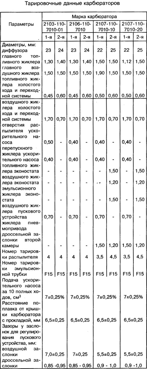
The carburetor 2105-1107010-20 is installed on VAZ-21063 cars, which differs from the carburetor 2107-1107010-20 only in the following calibration data: the diameters of the main fuel jets are 1.07 and 1.62 mm; diameters of the main air jets - 1.70 mm; the diameters of the nozzles of the pneumatic actuator of the throttle valve of the second chamber are 1.2 and 1.0 mm; air damper starting gaps - 5+0,5 mm, throttle - 0.7-0.8 mm.
A carburetor of the type "Solex" 21053-1107010 shown in pictures 10-11 of the album. This picture of the album shows the carburetor 2107-1107010-20.
Carburetor 2107-1107010-20 emulsion type, two-chamber, with a falling stream. The opening of the throttle valve of the first chamber is carried out from the pedal in the cabin. The carburetor has a balanced float chamber, two main dosing systems, a diaphragm starter, an economizer (econostat) with a pneumatic drive, a mechanically driven diaphragm accelerator pump, an independent idle system and a second mixing chamber transition system, as well as a spool device for crankcase ventilation.
Carburetor 2107-1107010-20 consists of three body parts: carburetor body 13, cover 17 and throttle body 54.
Cover 17 has inlet mouths of the mixing chambers. The air damper 32, needle valve 26, float 25, fuel filter 27 are installed in the cover.
A starter is attached to the cover. The lever 33 of the air damper is connected by a rod with a rail 35, and by a telescopic rod 34 with a three-arm lever 38. Economizer channels are made in the cover (econostat).
In the housing 13, in large diffusers, easily removable small diffusers 30 are installed, made integral with the sprayers of the 31 main dosing systems and the sprayer of the econostat. The housing contains channels for the main dosing systems, an autonomous idle system, a transition system, an accelerator pump, a communication channel for the starting device with the throttle space. The accelerator pump sprayer 19 is installed in the housing; fuel, air and emulsion jets of the above systems.
Shutters of the first and second chambers are installed in the housing 54. On the axis of the damper of the first chamber are installed: the lever 42 of the throttle actuator from the pedal, the lever 45, which limits the opening of the damper of the second chamber, the lever 46 of the connection with the air damper, the cam 4 of the accelerator pump drive. On the axis of the damper of the first chamber there is an engine crankcase ventilation valve. On the axis of the valve 51 there is a lever 49, rigidly fixed, and the lever 48 of the valve actuator, connected through a spring with the lever 49 and with the rod 47 of the diaphragm of the pneumatic actuator. In the body, channels of the transition system and an autonomous idle system are made, adjusting screws 11 and 9 of the mixture quantity and quality are installed (composition) idle mixture.