




Open large image in new tab »
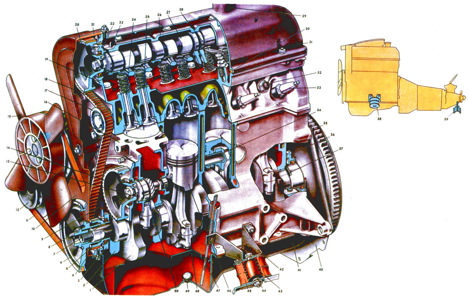
Fig. 3: 1. Crankshaft. 2. First main bearing cap. 3. Front crankshaft oil seal retainer. 4. Lower toothed belt cover. 5. Crankshaft toothed pulley. 6. Crankshaft pulley. 7. Crankshaft pulley key. 8. Ratchet. 9. Camshaft drive cover. 10. Middle toothed belt cover. 11. Fan, coolant pump and alternator drive belt. 12. Alternator pulley. 13. Oil pump and distributor drive shaft 14. Oil pump and distributor drive pulley 15. Engine cooling fan. 16. Cylinder block. 17. Toothed belt tension roller. 18. Camshaft drive toothed belt. 19. Cylinder head. 20. Camshaft pulley. 21. Upper toothed belt cover. 22. Camshaft oil seal retainer. 23. Mounting lug on camshaft bearing housing. 24. Exhaust valve. 25. Inlet valve. 26. Camshaft bearing housing. 27. Camshaft. 28. Valve actuator lever. 29. Cylinder head cover oil filler neck. 30. Cylinder head cover gasket. 31. Cylinder head cover. 32. Coolant temperature gauge sensor. 33. Spark plug. 34. Piston pin. 35. Flywheel with toothed rim, complete. 36. Crankshaft rear oil seal retainer. 37. Crankshaft thrust half ring. 38. Front engine mount. 39. Rear engine mount. 40. Front clutch housing cover. 41. Oil pan. 42. Front support bracket. 43. Front support spring. 44. Front support cushion buffer. 45. Front support rubber cushion. 46. Piston. 47. Oil level indicator. 48. Connecting rod with cover assembly. 49. Oil pan drain plug. 50. Oil pump and distributor drive shaft bushings.
The cars are equipped with a four-cylinder, four-stroke carburetor engine model 2105 with a belt drive of the camshaft. Some cars may be equipped with a 21011 engine with a chain drive of the camshaft. This album describes the 2105 engine.
The engine layout is simple and easy to maintain. All units requiring adjustment and maintenance (distributor, spark plugs, carburetor, air filter, etc.), installed in easily accessible places.
The engine cylinders are combined with the upper part of the crankcase and represent a single casting of the cylinder block. This arrangement ensures structural strength, rigidity, compactness, reliability and reduces the weight of the engine. In the lower part of the cylinder block, the crankshaft is mounted on five supports. The front and rear ends of the crankshaft are sealed with self-tightening rubber seals. Pistons 46 have two compression rings and one oil scraper ring with an expansion spring. The piston is connected to the connecting rod by a piston pin pressed into the upper head of the connecting rod. Each engine cylinder has one intake and one exhaust valve, which are actuated by camshaft 27, mounted on the cylinder head in an aluminum bearing housing 26. The upper location of the camshaft allows to reduce the weight of reciprocating moving parts and thereby ensure high reliability of the valve timing mechanism at high engine crankshaft speed.
The camshaft is driven from the crankshaft by means of a toothed belt 18. The valves are actuated by special levers 28.
The engine, complete with clutch and gearbox, forms the power unit and is mounted on the vehicle on three elastic supports. The supports support both the weight of the power unit and the loads that occur when the vehicle starts moving, accelerates and brakes. The design of the power unit suspension ensures minimal engine vibrations and eliminates the transmission of its vibrations to the body.
The engine is attached to the vehicle's front suspension crossmember by two front supports 38, and to the rear engine suspension crossmember by two rear supports 39.
The front supports have rubber cushions 45, in which steel washers with fastening bolts are vulcanized. To increase rigidity, springs are located in the opening inside the cushions, and to limit the travel, buffers 44 are used, which are a rubber rod with a vulcanized steel bushing.
The front support cushions are attached to the intermediate plates, and those, in turn, to the brackets 42 of the front engine support. The brackets are secured to the cylinder block flange with four studs. To protect the right cushion from the hot exhaust pipe, a protective casing is installed under it.
The rear support 39 consists of three steel plates vulcanized to the rubber separating them. The upper plate is attached to the rear cover of the gearbox, and the lower ones to the crossmember of the rear engine mount. To prevent the crossmember shelves from being dented when tightening the support mounting bolts, spacer bushings are installed between the shelves.
Cylinder block 16 is the basic part of the engine and serves to install and fasten mechanisms, devices and auxiliary units of the engine. The block is cast from special low-alloy cast iron. To increase rigidity, the lower plane is lowered by 50 mm below the crankshaft axis.
The cylinders of the block are divided by diameter into five classes, designated by the letters A, B, C, D and E, in increments of 0.01 mm. The cylinder diameters corresponding to these classes are as follows, in mm:
- A - 79,000-79,010
- B - 79,010-79,020
- C - 79,020-79,030
- D — 79,030-79,040
- E - 79,040-79,050
The cylinder class is indicated on the lower plane of the block opposite each cylinder. The cylinder and the piston mating with it must have the same class. During repair, the cylinders can be bored and honed to fit the increased piston diameter (by 0.4, 0.8 mm) taking into account the provision of a gap between the piston and the cylinder of 0.05-0.07 mm.
For repair of the crank mechanism, parts of repair sizes are produced: pistons and piston rings, increased in diameter by 0.4 and 0.8 mm; main and connecting rod bearing shells for crankshaft journals reduced in diameter by 0.25; 0,5; 0.75 and 1.00 mm.
The lower part of the cylinder block contains five main bearing supports of the crankshaft with thin-walled steel-aluminum liners. The bearings have removable covers 2, which are fastened to the block with self-locking bolts. The holes for the crankshaft bearings in the cylinder block are machined together with the covers. Therefore, the bearing covers are not interchangeable and for distinction, there are marks on their outer surface. For the covers of the first four bearings, the number of marks corresponds to the cover number. On the fifth cover, there are two marks with a large gap between them. The bearing supports and the corresponding covers are counted from the front end of the cylinder block.
On both sides of the rear main bearing, there are slots for installing thrust half rings 37, which hold the crankshaft from axial movements. A steel-aluminum half ring is installed on the front side of the bearing, and a metal-ceramic half ring is installed on the rear side (yellow color), impregnated with oil. It should be borne in mind that the grooves located on one side of the half rings should be facing the thrust surfaces of the crankshaft.
The value of the axial clearance of the crankshaft during engine assembly is provided within the range of 0.06-0.26 mm. If the clearance during operation exceeds the maximum permissible (0.35 mm), it is necessary to replace the thrust half rings with new ones or repair ones, increased by 0.127 mm.
In the front part of the cylinder block there is a cavity for the valve timing drive, separated from the engine crankcase by three oil seals and. The cavity is closed by three plastic covers 4, 10 and 21. A holder 36 of the rear oil seal is attached to the cylinder block from the rear side.
On the left side of the cylinder block, the oil filter and fuel pump are attached, the crankcase ventilation system and oil pressure sensor are installed. On the right side, the coolant pump and generator are installed on the cylinder block. On the upper plane of the block, in its front left part, the ignition distributor is installed.
The cylinder block is closed from below by a stamped steel crankcase 41. The crankcase has a partition to calm the oil. A gasket made of a cork-rubber mixture is installed between the crankcase and the cylinder block. A plug 49 is provided for draining the oil from the crankcase. A permanent magnet is installed in the plug, which attracts small steel particles that get into the oil during engine operation.
The cylinder head 19 is common for four cylinders, cast from aluminum alloy, and above each cylinder there are wedge-shaped combustion chambers. Each chamber has a threaded hole for the spark plug. On the left side in the front and rear parts of the cylinder head there are channels for draining oil into the oil pan. Valve seats made of special cast iron are pressed into the head to ensure high strength under impact loads. The dimensions of the inlet valve seat are larger than the dimensions of the exhaust valve seat. The working chamfers of the seats are machined after pressing in assembly with the cylinder head to ensure precise alignment of the chamfers with the holes of the valve guide bushings.
The valve guides are also made of cast iron and are pressed into the cylinder head with interference. Spiral grooves for lubrication are cut into the holes in the guides. The inlet valve guides have grooves cut to half the length of the hole, and the outlet valve guides have grooves cut along the entire length of the hole.
The article is copied from the website: VazBook
Between the head and the cylinder block there is a gasket made of asbestos material on a metal frame and impregnated with graphite. Along the edges of the holes for the cylinders, the gasket has a border made of soft steel. The opening of the oil supply channel to the camshaft is edged with copper tape. To prevent the gasket from sticking to the block and cylinder head, it is recommended to rub it with graphite before assembly.
The cylinder head is attached to the cylinder block with eleven bolts. To ensure uniform and tight fit of the head to the cylinder block and to prevent warping, the bolts must be tightened on a cold engine in two stages using a torque wrench and in a strictly defined sequence (from the center to the periphery, left and right alternately). In the first step, preliminary tightening is performed with a tightening torque of approximately 39.2 N·m (4 kgf·m). In the second step, final tightening is performed with a torque of 112.7 N·m (11.5 kgf·m).
The cylinder head mounting bolts should be tightened after the first 2000-3000 km, and subsequently after removing the cylinder head or when signs of gas leakage or coolant leakage between the block and the cylinder head appear.
The cylinder head is closed from above by cover 31. The cover is cast from aluminum. In the upper part of the cover there is a neck for filling the engine with oil. To eliminate oil leakage, a gasket is installed between the cylinder head and the cover. The cover is attached to the cylinder head with studs and nuts.