
These two unified engines with a working volume of 649 and 750 cm3 different pistons and cylinder block (various diameters of inlet ports and valves), cylinder head gasket (various bore diameters for cylinders) and carburetors (various calibration data). In addition, there are differences in the size of the balancing masses of the flywheel, the generator drive pulley and the balancing shafts.
Engines with a compression ratio of 9.9 run on AI-93 motor gasoline with an octane rating of at least 93 according to the research method.
High power and economic indicators of engines are achieved through the use of a compact combustion chamber, a two-chamber carburetor, the selection of adjustments for power and ignition systems, the selection of the shape of the inlet and outlet channels, valve timing, and a decrease in mechanical losses in the engine as a whole.
The engine cylinders are combined with the upper part of the crankcase and are a single casting - the cylinder block. With this arrangement, the strength of the structure, its rigidity, compactness, reliability are ensured, and the mass of the engine is also reduced.
A crankshaft is mounted on three bearings at the bottom of the cylinder block. The front and rear ends of the crankshaft are sealed with self-clamping rubber seals.
Each engine cylinder has one intake and one exhaust valve. Pistons 25 have two compression rings and one oil scraper with a spring. The piston is connected to the connecting rod with a piston pin pressed into the upper head of the connecting rod.
The camshaft 12 is mounted on the cylinder head and is driven from the crankshaft by a toothed belt 10. The advantage of the drive is the simplicity of design and lower weight compared to other types of gears.
For two-cylinder engines (what are mod engines. 1111 and 11113) the balance of the moving masses of the crank mechanism is worse compared to the four-cylinder ones. Hence, the level of engine vibrations is higher. If appropriate measures are not taken, these vibrations will have a negative impact on both the car body and passengers. Therefore, to reduce vibrations on engines mod. 1111 and 11113 have two balance shafts 31 on the right and left side of the engine, which are driven by gears from the crankshaft. These shafts have unbalanced masses and, as they rotate, compensate for inertial forces from the piston and connecting rod. In addition, to reduce vibrations on the flywheel 28 and the pulley 5 of the generator drive, one-sided tides are made. As a result of such design measures, the vibration of the engines is reduced to an acceptable level.
Since the engines 1111 and 11113 have different masses of pistons, they respectively have different imbalances of the balance shafts, flywheel and generator drive pulley. Therefore, there are marks on these parts of the 11113 engine to distinguish them. On the flywheel there is an annular groove with a diameter of 135 mm from the side of attachment to the crankshaft. Balance shafts have an annular groove near the seating surface for the rear bearing. An annular groove with a diameter of 120 mm is machined on the rear side of the alternator drive pulley.
Cylinder block
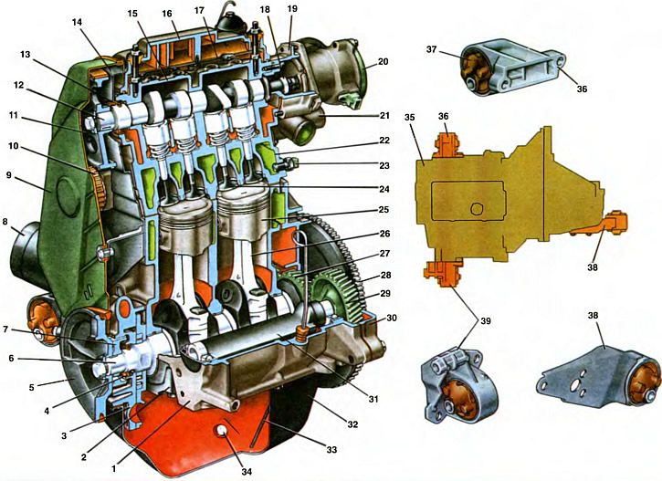
1. Cylinder block. 2. Cover of the first main bearing. 3. Oil pump. 4. Front crankshaft oil seal. 5. Generator drive pulley. 8. Crankshaft. 7. Camshaft drive pulley. 8. Oil filter. 9. Front protective cover of the toothed belt. 10. Camshaft drive belt. 11. Camshaft pulley. 12. Camshaft. 13. Camshaft seal. 14. Back curled toothed belt cover. 15. Camshaft bearing housing. 18. Cylinder head cover. 17. Oil separator cover. 18. Eccentric for driving the fuel pump. 19. Housing of auxiliary units. 20. Sparking torque sensor. 21. Outlet pipe of the cooling jacket. 22. Cylinder heads. 23. Coolant temperature indicator sensor. 24. Inlet valve. 25. Piston. 26. Connecting rod. 27. Balance shaft drive gear. 28. Flywheel. 29. Balance shaft gear. 30. The holder of a back epiploon of a cranked shaft. 31. Balance shaft. 32. Oil sump. 33. Oil level indicator. 34. Oil drain plug. 35. Power unit (engine with gearbox and clutch). 38. Bracket with support for the rear engine mount. 37. Engine mount. 38. Bracket with support for the left engine mount. 39. Bracket with support for the front engine mount.
Cylinder block 1 is the basic part of the engine and serves to install and fasten mechanisms, devices and auxiliary units of the engine. The block is cast from special low-alloy cast iron.
The coolant channels are made along the entire height of the cylinders, which improves the cooling of the pistons and piston rings and reduces block deformation from uneven heating.
To increase rigidity, the lower plane of the block is lowered 53 mm below the crankshaft axis. The cylinders of the block are divided by diameter into five classes through 0.01 mm, denoted by the letters A, B, C, D, E:
| Class | Engine cylinder diameter 1111, mm | Engine cylinder diameter 11113, mm |
| A | 76,000...76,010 | 82,000...82,010 |
| IN | 76,010...76,020 | 82,010...82.020 |
| WITH | 76,020...76,030 | 82,020...82,030 |
| D | 76,030...76,040 | 82,030...82,040 |
| E | 76,040...76,050 | 82,040...82,050 |
The cylinder class is indicated on the bottom plane of the block against each cylinder.
The cylinder and the piston mating with it must be of the same class. During repair, the cylinders can be bored and honed to fit an increased piston diameter of 0.4 and 0.8 mm.
In the lower part of the cylinder block there are three crankshaft main bearing supports with thin-walled steel-aluminum liners. Bearings have removable covers 2, which are attached to the block with self-locking bolts. The holes for the crankshaft bearings in the cylinder block are machined complete with covers, which ensures high accuracy, the correct geometric shape of the holes and their alignment.
The middle main bearing shells are made without a groove on the inner surface. The shells of the extreme main bearings until 1997 were grooved on the inner surface (both upper and lower). Since 1997, the lower shells of the outermost main bearings have been installed without a groove.
Bearing caps are not interchangeable and have marks on the outer surface (see ch. 9). Bearing supports and their corresponding covers are measured from the front end of the cylinder block. The covers are located so that the marks are on the side of the generator installation.
In the middle support there are sockets for installing thrust half rings that hold the crankshaft from axial movement. The value of the axial clearance should be 0.06...0.26 mm. If the clearance exceeds the maximum allowable (0.35 mm), it is necessary to replace the half-rings with repair ones, increased by 0.127 mm. It should be borne in mind that the grooves located on one side of the half rings must face the thrust surfaces of the crankshaft.
The cylinder block is closed from below with a stamped steel crankcase 32. The crankcase has a baffle to calm the oil. Between the oil sump and the cylinder block, a cork-rubber mixture gasket is installed.
On the rear side, the holder 30 of the rear oil seal is attached to the cylinder block. The holder, pre-assembled with the oil seal, is installed on the cylinder block with the crankshaft in it and the main bearing caps tightened. The holder is attached to the cylinder block with bolts with spring washers.
The cavity of the coolant pump is located in the front right side of the cylinder block jacket. An oil filter 8 is attached below it. A generator is installed on the left side of the cylinder block. In the lower part on the left there is a lug for mounting the engine on the suspension bracket.
In the front part of the cylinder block, an oil pump 3 is installed through the gasket, in the cover of which the front crankshaft oil seal 4 is located.
The exact position of the oil pump relative to the cylinder block and crankshaft is ensured by two dowel pins pressed into the pump housing, which fit into the corresponding holes in the cylinder block.
Covers 9 and 14 are attached to the front end of the cylinder block, forming a cavity for the timing belt 10.
The clutch housing is attached to the rear end of the cylinder block. The exact position of the crankcase relative to the cylinder block and the alignment of the crankshaft and the input shaft of the gearbox are provided by two centering bushes pressed into the cylinder block.
Cylinder head
The cylinder head 22 is cast from an aluminum alloy and has a wedge-shaped combustion chamber. Guide bushings and valve seats made of cast iron are pressed into the head. The intake valve seat is larger than the exhaust valve seat. The seats, pre-cooled in liquid nitrogen, are inserted into the seats of the heated cylinder head. This ensures a secure and firm fit of the seats in the head. The seat faces are ground after they are installed in the head, concentric with the holes in the valve guides. A special non-shrink gasket on a metal frame is installed between the head and the cylinder block.
The head is centered on the cylinder block with two bushings and is attached to it with six bolts. To uniformly compress the entire surface of the block gasket, to ensure reliable sealing and avoid tightening the bolts during subsequent maintenance of the vehicle, the cylinder head bolts are tightened evenly without jerks in four steps and in a strictly defined (shown on sheet 10) sequences:
- technique 1 - tighten the bolts with a torque of 2 kgf·m;
- technique 2 - tighten the bolts with a torque of 7.08... 8.74 kgf·m;
- reception 3 - turn the bolts 90°;
- reception 4 - again tighten all the bolts by 90°.
In the upper part of the cylinder head there are three bearings for the camshaft journals 12. The bearings are split. The upper half is located in the bearing housing 15, and the lower half is in the cylinder head. The locating sleeves of the camshaft bearing housing are located at the housing mounting studs. The bearing bores are machined complete with the bearing housing and therefore the cylinder head can only be replaced complete with the bearing housing.
Sealant of the KLT-75T type is applied on the surfaces of the cylinder head mating with the bearing housing in the area of the extreme camshaft bearings.
Install the bearing housing and tighten the nuts of its fastening in two steps:
- 1st reception - pre-tighten the nuts in the sequence indicated on sheet 10 until the surfaces of the bearing housing touch the cylinder head. Housing mounting sleeves must freely enter their sockets;
- 2nd reception - finally tighten the nuts with a torque of 2.2 kgf·m in the same sequence.
In the upper part of the head there are four sockets with a diameter of 35.320... 36.345 mm for valve lifters.
From above, the cylinder head is closed with a cast aluminum cover 16 with a gasket.
The housing of auxiliary units 19 is attached to the rear end of the cylinder head.
The engine assembly with the clutch and gearbox forms a power unit, which is mounted on the subframe of the car on three elastic supports. The supports perceive both the mass of the power unit and the loads that occur when the car starts off, accelerates and brakes. The mounts reduce body vibration during engine operation, ensure minimal engine vibrations, and also protect the engine from shock loads when the vehicle is moving over uneven roads. The location of the supports, taking into account the center of gravity of the engine and the power unit, helps to reduce the transmission of vibration to the body. The design of the engine mount eliminates the possibility of direct contact of engine parts with the body, which significantly reduces the transmission of noise and knocks of a running engine inside the body.
Valve timing
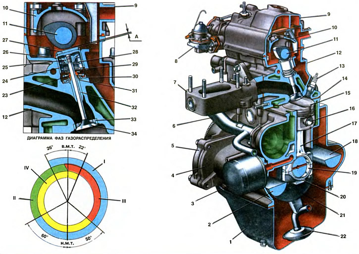
1. Oil sump. 2. Right balance shaft. 3. Oil filter. 4. Cylinder block. 5. Rear oil seal holder. 6. Coolant pump inlet pipe. 7. Inlet pipe. 8. Fuel pump. 9. Cylinder head cover. 10. Camshaft bearing housing. 11. Camshaft. 12. Cylinder head. 13. Spark plug. 14. Cylinder head gasket. 15. Piston. 16. Piston pin. 17. Connecting rod. 18. Left balance shaft. 19. Insert connecting rod bearing of the crankshaft. 20. Connecting rod cap. 21. Crankshaft. 22. Oil filter receiver. 23. Oil cap. 24. Valve lifter. 25. Valve cracker. 28. Valve spring plate. 27. Adjusting washer. 28. Internal valve spring. 29. Outer valve spring. 30. Support washer springs. 31. Retaining ring. 32. Valve guide. 33. Valve seat. 34. Inlet valve.
A - clearance in the valve drive mechanism on a cold engine: 0.15-0.25 mm for intake valves and 0.3-0.4 mm for exhaust valves.
I - inlet of the combustible mixture
II - compression
III - working stroke
IV - exhaust gases
In one working cycle, four cycles occur in the engine cylinder: the intake of a combustible mixture, compression, power stroke and exhaust gases. These cycles are carried out in two revolutions of the crankshaft.
The intake valve begins to open before the piston reaches top dead center (V. m. t.), i.e., in the piston position corresponding to 26°of rotation of the crankshaft to c. m. t. This is necessary in order for the valve to be fully open (when the piston goes down in the intake stroke of the combustible mixture) and as much fresh fuel mixture as possible would enter through the fully open inlet.
The intake valve closes after the piston has passed bottom dead center (n. m. t.), i.e., in a position corresponding to 60°of rotation of the crankshaft after n. m. t. Due to the inertial pressure of the jet of the combustible mixture being sucked in, it continues to flow into the cylinder when the piston has already begun to move upward, and thus the best filling of the cylinder is ensured. Thus, the intake practically takes place in a time corresponding to a rotation of the crankshaft by 266°.
The exhaust valve begins to open even before the full end of the working stroke, before the piston approaches n. m.t., i.e., in a position corresponding to 50°rotation of the crankshaft BC. m. t. At this moment, the pressure in the cylinder is still quite high and the gases begin to intensively flow out of the cylinder, as a result of which their pressure and temperature drop rapidly. This greatly reduces the engine work required to release gases and prevents the engine from overheating.
The release continues after the piston has passed through. m.t., i.e. when the crankshaft rotates 22°after c. m. t. Thus, the release cycle is 252°.
From the valve timing diagram, it can be seen that there is such a moment (48°crankshaft rotation approx. m. t.), when both valves are open at the same time - inlet and outlet, i.e., the exhaust and intake strokes are carried out with overlapping valves. Due to the short time interval and low pressure drops, the overlapping of the valves does not lead to the penetration of exhaust gases into the intake pipe, but, on the contrary, the vacuum in the cylinder due to the inertia of the exhaust gas flow causes the combustible mixture to be sucked into the cylinder and thereby improves its filling.
The described valve timing takes place with a gap A between the camshaft cam and the valve tappet on a cold engine.
To ensure that the opening and closing times of the valves are matched to the corresponding piston positions determined by the angles of rotation of the crankshaft (i.e. to ensure the correct installation of the valve timing), there are marks on engine parts (see ch. 10):
- a - on the gear pulley of the crankshaft drive;
- b - on the cover of the oil pump;
- c - on the generator drive pulley;
- d and e - on the front cover of the toothed belt;
- e - on the back cover of the toothed belt;
- g - on the camshaft pulley.
If the valve timing is set correctly, then when the piston of the first cylinder is in c. m.t. at the end of the compression stroke, mark e on the back cover of the toothed belt must match mark w on the camshaft pulley, and mark a on the crankshaft drive gear pulley should match mark 6 on the oil pump cover.
When the camshaft drive cavity is closed by the front cover, the position of the crankshaft can be determined by the marks c and e on the alternator drive pulley and the timing belt front cover. With the position of the pistons in m.t. the mark in on the alternator drive pulley must match the mark d on the camshaft drive cover.
If the marks match, the belt tension and clearances A in the valve mechanism are adjusted.
Gap A between the camshaft cams and shims on a cold engine should be 0.15... 0.25 mm for intake valves and 0.3... 0.4 mm for exhaust valves. The gap is set by selecting the thickness of the shim 27.
Spare parts are supplied with shims with a thickness of 3 to 4.5 mm at intervals of every 0.05 mm. The thickness of the washer is marked on its lower surface with an electrograph.
If the gaps differ from the specified values, then the valve timing diagram is distorted: with an increased gap, the valves open with a delay and close ahead, and with an insufficient gap, they open ahead and close with a delay. If there is no gap, then the valves remain slightly ajar all the time, which drastically reduces the life of the valves and seats.
The gaps between the cams and the washers of the pushers are set with the cover 9 of the cylinder head and the front protective cover of the toothed belt removed, the spark plugs turned out and without oil in the oil baths of the cylinder head in the following order.
The crankshaft is turned clockwise until the alignment marks on the camshaft pulley and the back cover of the toothed belt are aligned, and then it is turned another 40... 50° (2.5...3 teeth on the camshaft pulley). In this case, in the first cylinder - the combustion phase. The crankshaft should be rotated by the bolt securing the alternator drive pulley.
With a set of probes, check the clearance at the 1st camshaft cam. If the gap differs from the norm, then using the device, the valve pusher is sunk and fixed in the lower position. With a micrometer, measure the thickness of the removed shim. Then determine the thickness of the new washer according to the formula: H = B + (A - C), where H is the thickness of the new washer; A - measured gap; B is the thickness of the removed washer; C is the nominal gap.
Example
Let's say A \u003d 0.26 mm; B = 3.75 mm; C = 0.2 mm (for intake valve). Then: H = 3.75 + (0,26 — 0,2) = 3.81 mm. Within the clearance tolerance of±0.05 mm, we accept the thickness of the new washer equal to 3.8 mm.
A new adjusting washer is installed in the valve lifter, the retainer is removed and the clearance is checked again. If it is adjusted correctly, then the probe with a thickness of 0.2 or 0.35 mm should come out with a slight pinch. Sequentially turning the crankshaft half a turn, which corresponds to turning the mark on the camshaft pulley by 90°, adjust the clearances for the remaining valves, according to the sequence indicated in the table:
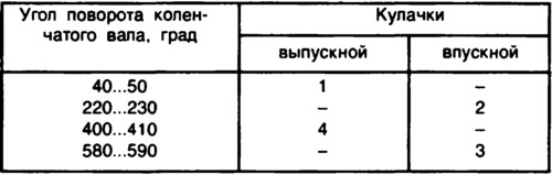
The cam numbers are counted in order from the camshaft pulley.
Engine operation order
For smooth operation of the engine and reduction of uneven loads on the crankshaft, work processes in various cylinders must occur in a certain sequence. The sequence of alternation of the same cycles in different cylinders of the engine is called the order of its operation.
The order of operation of the engine cylinders depends on the location of the crankshaft journals and camshaft cams. The sequence of alternation of strokes in the engine cylinders, flowing for two complete revolutions of the crankshaft, is indicated in the table:
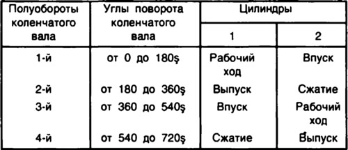
When in the first cylinder the piston moves down in the range from 0°to 180°of rotation of the crankshaft, combustion and expansion of gases occur. During expansion, gases do useful work, so this cycle is called a working stroke. In the second cylinder, lagging behind the first by 360°, the piston moves down and the combustible mixture is admitted.
Similarly, in the range from 180°to 360°of rotation of the first crankpin, compression occurs in the second cylinder and exhaust in the first, etc.
When developing a family of engines and their systems for the new model, the designer set himself three main tasks: reducing weight and dimensions, reducing fuel consumption and meeting a set of environmental protection requirements. The reduction in weight and dimensions was ensured by the compact design of the mechanisms and engine systems. The improvement in engine efficiency is achieved by the organization of the working process at high (9,9) compression ratio and other measures previously discussed. The design of the engine and its systems ensures that the requirements for toxicity of exhaust gases are met.
Reduced clearances between the piston and cylinder, in the crankshaft bearings, as well as the design of the valve drive with minimal clearances between the pushers and their guides in the cylinder head, better balance of the crankshaft, and the introduction of balancing shafts contributed to the solution of the problem of noise reduction.
The transmission of vibrations and noise has also been reduced due to the fact that the fastening of the aluminum cylinder head cover is vibration-isolated, on rubber bushings.