
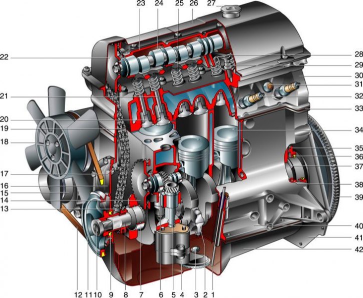
Engine VAZ-21213: 1 - oil level indicator; 2 - connecting rod; 3 - drain plug of the oil pan; 4 - oil pump; 5 – a gear wheel of a drive of the oil pump; 6 - oil pump drive roller; 7 - insert of the main bearing of the crankshaft; 8 - crankshaft; 9 – a forward epiploon of a cranked shaft; 10 - pulley fastening nut; 11 - crankshaft pulley; 12 – a belt of a drive of the pump of a cooling liquid; 13 - crankshaft sprocket; 14 – an asterisk of a drive of the oil pump; 15 - generator pulley; 16 – a cover of a drive of a camshaft; 17 - chain tensioner shoe; 18 - fan impeller; 19 – a chain of a drive of a camshaft; 20 - exhaust valve; 21 - inlet valve; 22 - camshaft sprocket; 23 - camshaft bearing housing; 24 - camshaft; 25 - valve springs; 26 – a cover of a head of the block of cylinders; 27 - oil filler cap; 28 - valve lever (rocker); 29 - adjusting bolt; 30 – a head of the block of cylinders; 31 - coolant temperature indicator sensor; 32 - spark plug; 33 – laying of a head of the block of cylinders; 34 - piston; 35 – the holder of a back epiploon; 36 – a back epiploon of a cranked shaft; 37 - thrust half ring of the crankshaft; 38 - cover of the main bearing; 39 - flywheel; 40 - cylinder block; 41 - clutch housing cover; 42 - oil pan.
Petrol, four-stroke, four-cylinder, eight-valve, in-line, with an overhead camshaft. The power system is carburetor. The order of operation of the cylinders: 1-3-4-2, counting - from the crankshaft pulley.
The engine with a gearbox and clutch forms a power unit - a single unit mounted in the engine compartment on three elastic rubber-metal supports.
Right side of the engine (along the car) located: intake pipe and exhaust manifold with exhaust gas recirculation system, generator, thermostat, starter (on the clutch housing), carburetor and air filter housing. On the left are located: the sensor-distributor ignition (distributor), spark plugs and high voltage wires, oil level gauge, oil filter, fuel pump, coolant temperature and oil pressure sensors. Front: coolant pump and alternator drive (V-belt), fan impeller.
The cylinder block is cast from special low-alloy cast iron, the cylinders are bored directly in the block. The nominal diameter is 82 mm, during repairs it can be increased by 0.4 or 0.8 mm. The cylinder class is marked in Latin letters on the lower plane of the block in accordance with the cylinder diameter in mm: A - 82.00-82.01, B - 82.01-82.02, C - 82.02-82.03, D - 82.03–82.04; E, 82.04–82.05. The maximum allowable cylinder wear is 0.15 mm per diameter.
At the bottom of the cylinder block there are 5 main bearing supports with removable covers, which are attached to the block with special bolts. The holes in the cylinder block for bearings are machined with the covers installed, so the covers are not interchangeable and are marked with risks on the outer surface to distinguish them. In the rear support there are sockets for thrust half rings that prevent axial movement of the crankshaft. A steel-aluminum half ring is installed in front (white color), and behind - ceramic-metal (yellow). In this case, the grooves on them should be facing the crankshaft. Half rings are supplied in nominal and 0.127 mm oversized sizes. If the axial clearance (backlash) crankshaft is out of range of 0.06-0.26 mm, then replace one or both half rings (the maximum allowable clearance in operation is 0.35 mm).
The liners of the main and connecting rod bearings are thin-walled steel-aluminum. Upper main bearing shells (installed in the cylinder block) 1, 2, 4 and 5 supports - with a groove on the inner surface. The lower shells of the main bearings and the upper shell of the third bearing are without a groove, as are the shells of the connecting rod bearings. Repair liners are produced for crankshaft journals, reduced by 0.25, 0.5, 0.75 and 1.00 mm. The nominal calculated diametrical clearance between the crankshaft journals and the bearing shells should be 0.026–0.073 mm for the main bearings, 0.02–0.07 mm for the connecting rod bearings, the maximum allowable clearance between the journals and the bearing shells is 0.15 mm and 0.1 mm respectively.
The crankshaft is made of high-strength cast iron, has 5 main journals and 4 connecting rods. The shaft is equipped with eight counterweights cast integrally with the shaft (fully counterbalanced). To supply oil from the main journals to the connecting rods, channels are drilled in it, closed with pressed and stamped plugs. These channels also serve to clean the oil: under the action of centrifugal force, solid particles and resins that have passed through the filter are thrown to the plugs. Therefore, when repairing the shaft and when balancing, be sure to clean the channels from accumulated deposits. Plugs cannot be reused - they are replaced with new ones.
At the front end (sock) On the crankshaft, a timing gear drive sprocket and a drive pulley for the generator and coolant pump are installed on the segment key. The pulley is sandwiched between the nut at the front end of the shaft and the sprocket. The front crankshaft oil seal installed in the camshaft drive cover, cast from aluminum alloy, works on its surface. The rear oil seal is pressed into a holder, also cast from aluminum alloy, which is attached to the rear end of the cylinder block. The oil seal runs on the surface of the crankshaft flange. The front bearing of the input shaft of the gearbox is pressed into the rear end of the crankshaft.
A flywheel is attached to the crankshaft flange with six self-locking bolts through a common washer. It is cast iron and has a pressed steel ring gear for starting the engine with a starter. The flywheel is installed so that the cone-shaped hole near its crown is opposite the connecting rod journal of the 4th cylinder - this is necessary to determine the TDC after assembling the engine.
Connecting rods - steel, I-section, processed together with covers. In order not to confuse the covers during assembly, the cylinder number is stamped on them, as well as on the connecting rods (it should be on the same side of the connecting rod and cap). Special bolts are pressed into the holes of the lower head of the connecting rod; when disassembling, they must not be knocked out of the head. A steel-bronze bushing is pressed into the upper head of the connecting rod. According to its diameter, connecting rods are divided into three classes with a step of 0.004 mm. The class number is stamped on the connecting rod cap. Also, connecting rods are divided into classes by weight, which is marked with paint or a letter on the connecting rod cover. All engine connecting rods must be of the same weight class.
Piston pin - steel, tubular section, floating type (rotates freely in the piston bosses and in the connecting rod head), from falling out is fixed by two locking spring rings located in the grooves of the piston bosses. According to the outer diameter, three classes of fingers are distinguished (through 0.004 mm), which are marked with paint: 1 - blue (the thinnest), 2 – green, 3 – red.
The piston is made of aluminum alloy. The piston skirt has a complex shape: in the longitudinal section it is conical, and in the transverse section it is oval. Three grooves for piston rings are machined in the upper part of the piston. The oil scraper ring groove has drillings for supplying oil collected by the ring from the cylinder walls to the piston pin. The hole for the piston pin is offset by 1.2 mm from the diametral plane of the piston, therefore, when installing the piston, it is necessary to navigate along the embossed arrow on its bottom: it must be directed towards the crankshaft pulley.
By outside diameter (measured in a plane perpendicular to the axis of the piston pin, at a distance of 55 mm from the piston crown) pistons, like cylinders, are divided into 5 classes (lettering on the bottom). Piston diameter in mm (for nominal size): A - 81.965-81.975, B - 81.975-81.985, C - 81.985-81.995, D - 81.995-82.005, E - 82.005-82.015. Pistons of classes A, C and E are available as spare parts (nominal and repair dimensions), which is quite enough to match the piston to the cylinder: the calculated diametral clearance between them is 0.025–0.045 mm, and the maximum allowable wear clearance is 0.15 mm. At the same time, it is not recommended to install a new piston in a worn cylinder without boring it: the groove for the upper piston ring in the new piston may be slightly higher than in the old one, and the ring will break about «step», formed in the upper part of the cylinder when it is worn. At pistons of repair dimensions, a triangle is knocked out on the bottom (increase in diameter by 0.4 mm) or square (increase in diameter by 0.8 mm).
By hole diameter (in mm) under the piston pin, pistons are divided into 3 classes: 1 - 21.978 - 21.982, 2 - 21.982 - 21.986, 3 - 21.986 - 21.990. The class number is also stamped on the piston crown. New pin, piston and connecting rod must be of the same class. When replacing, parts are selected: a finger lubricated with engine oil must enter the hole in the piston and the upper head of the connecting rod from the force of the hand and not fall out of them under its own weight.
The pistons of the 21213 engine are produced in the same mass class, so they do not need to be selected separately.
Piston rings are located in the piston grooves. The top two rings are compression. They prevent the breakthrough of gases into the crankcase and contribute to the removal of heat from the piston to the cylinder. The bottom ring is oil scraper. Oil collected from the walls of the cylinder is supplied to the holes in the piston bosses and serves to lubricate the piston pin.
The height gap between the piston rings and the grooves on the piston is measured with a set of feeler gauges. Nominal clearance: for the upper compression ring - 0.04–0.07 mm, for the lower one - 0.03–0.06 mm, for the oil scraper - 0.02–0.05 mm. The maximum allowable wear gaps are 0.15 mm. The gap in the lock of the rings is measured by inserting the rings into a special gauge or into the engine cylinder, and aligning them with the piston head. The gap in the lock for all rings should be 0.25–0.45 mm.
The cylinder head is made of aluminum alloy, common to all four cylinders. It is centered on the cylinder block with two bushings and fastened with 11 bolts. If the length of the bolt shaft exceeds 120 mm, then it should be replaced with a new one. A non-shrink metal-reinforced gasket is installed between the block and the head. Reuse is not allowed.
In the upper part of the cylinder head, an aluminum camshaft bearing housing is fixed on nine studs. It is centered on two bushings put on the extreme studs.
Camshaft - cast, cast iron, five-bearing, with bleached cams; driven by a double row chain from the crankshaft sprocket. Axial movement is limited by a thrust flange included in the groove of the front bearing journal of the shaft. For the correct installation of the camshaft relative to the crankshaft, there are marks on the sprockets. If the mark on the crankshaft pulley matches the mark on the camshaft drive cover, then the mark on the camshaft sprocket must align with the protrusion on the bearing housing. The camshaft sprocket is installed in only one position and is tightened with a bolt with support and locking washers. The tendril of the latter enters the hole in the sprocket, and the side part is bent to the edge of the nut.
Seats and valve guides are cast iron, pressed into the cylinder head. Repair sleeves with an outer diameter increased by 0.2 mm are supplied as spare parts. The holes in the bushings are finally processed with a reamer after pressing. The bore diameter of the inlet valve bushings is 8.022–8.040 mm, the exhaust valves are 8.029–8.047 mm. Grooves for lubrication are cut on the inner surface of the bushings: for the inlet valve bushings - for the entire length, for the exhaust valves - up to half the length of the hole. Oil caps are put on top of the bushings (valve seals) made of oil-resistant rubber with a steel bracelet spring.
Valves - steel; outlet - with a head made of heat-resistant steel with welded chamfer. They are arranged in a row, inclined to the plane passing through the axis of the cylinders. Inlet valve plate wider (37 mm), than graduation (31.5mm). Valves are driven by camshaft cams through levers («rockers»). One end of the lever rests on the spherical head of the adjusting bolt, and the other end acts on the end of the valve stem. The levers are pressed against the heads of the bolts by springs included in the groove on the heads of the levers. The valve closes under the action of two oppositely coiled springs installed coaxially (coaxially).
Their lower ends rest on the support washers, and their upper ends rest on a plate, which is fixed with two cone crackers that enter the groove at the end of the valve stem. Valve clearance (0.15 mm for inlet and 0.20 mm for outlet) is adjusted by screwing in or out of the adjusting bolt, which, after the end of the adjustment, is locked with a lock nut.
To reduce fluctuations in the timing chain, a plastic damper is installed on its left branch between the oil pump drive shaft sprocket and the camshaft sprocket on two bolts. To prevent the chain from falling into the crankcase when removing the camshaft sprocket, a limiting pin is screwed into the cylinder block to the right of the crankshaft sprocket. The right branch of the chain is tensioned by a semi-automatic spring tensioner mounted on two studs in the cylinder head. To tension the chain, loosen the cap nut of the tensioner and turn the engine crankshaft. In this case, the tensioner plunger under the action of the spring rests against the rubber-metal shoe, pulling the chain. Tighten the nut after adjustment. Jerks and small vibrations of the chain during operation are damped due to the plunger device of the tensioner, which ensures that its shank is recessed under load by 0.2–0.5 mm. The tensioner shoe rotates on an axle screwed into the cylinder block.
The timing chain also drives the oil and fuel pump drive shaft, as well as the ignition distribution sensor. The fastening of its sprocket is similar to the fastening of the camshaft sprocket. The sizes of the stars are also the same.
The roller rotates in bushings in the cylinder block, and is kept from axial movements by a thrust flange, which is included in the groove on its front neck. The ring gear of the roller engages with the gear of the oil pump drive and the ignition distribution sensor, installed vertically in the sleeve in the groove of the cylinder block. The gear has a slotted longitudinal hole, into which the splined end of the oil pump shaft enters from below, and the splined end of the ignition sensor-distributor shaft from above.
Oil pump - gear, single-stage, with a pressure reducing valve; mounted in a housing attached to the bottom of the cylinder block. The suction pipe is molded integrally with the lower part of the body and is closed with a stamped perforated mesh for coarse oil cleaning from mechanical impurities. Nominal clearances: between gear teeth - 0.15 mm, between gears (by outside diameter) and the walls of the pump housing - 0.11–0.18 mm, between the ends of the gears and the plane of the housing - 0.066–0.161 mm; limit clearances, respectively - 0.25 mm, 0.25 mm and 0.20 mm (measured with a set of probes). Nominal clearances between the driven gear and its axis - 0.017–0.057 mm, between the pump shaft and the hole in the housing - 0.016–0.055 mm; maximum allowable gaps - 0.10 mm (determined by measurements of details).
Engine lubrication - combined: main and connecting rod bearings, pairs are lubricated under pressure «support - camshaft journal», bearings (bushings) oil pump drive shaft and gear; oil is sprayed onto the cylinder walls (further to the piston rings and pins), to a couple «camshaft cam - lever» and valve stems; the remaining nodes are lubricated by gravity. Oil filter - full-flow, non-separable, with bypass and anti-drain valves.
The crankcase ventilation system is closed, forced, with exhaust gases through the oil separator.
Power supply, cooling, exhaust and ignition systems are described in the relevant sections.