




Open large image in new tab »
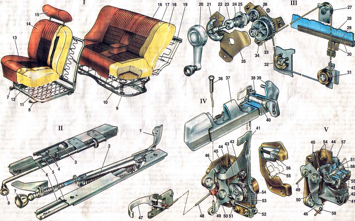
Fig. 33. Body equipment.
1. Front seat back reinforcement; 2. Backrest tilt mechanism spring; 3. Roller; 4. Crawlers' balls; 5. Sled sliders; 6. Slide guides; 7. Screw with handle of backrest tilt mechanism; 8. Seat movement mechanism handle; 9. Seat cushion fixing hole; 10. Padding backing; 11. Frame spring; 12. Pillow frame; 13. Pillow; 14. Back; 15. Headrest; 16. Rear seat back upholstery; 17. Upholstery lining; 18. Back padding; 19. Rear seat back frame; 20. Window lifter handle; 21. Handle lining; 22. Leading roller; 23. Brake spring leash; 24. Brake spring; 25. Drive shaft support; 26. Drive gear; 27. Upper roller; 28. Drop-down door glass; 29. Gasket; 30. Glass frame; 31. Bottom roller; 32. Tension roller; 33. Drum with driven gear; 34. Window regulator housing; 35. Housing cover; 36. Lock button; 37. External door handle; 38. Lock switch leash; 39. External handle housing; 40. Lock switch; 41. External lock drive lever; 42. External drive lever spring; 43. Ratchet; 44. Lock body; 45. Locking lever spring; 46. Internal lock drive lever; 47. Internal door handle; 48. Inner drive rod; 49. Lock button pull; 50. Lock lever; 51. Central roller; 52. Lock release roller; 53. Lock switch rod; 54. Ratchet spring; 55. Rotor; 56. Lock retainer cracker; 57. Thrust washer; 58. Central shaft bushing; 59. Intermediate rod of the internal drive; I. Seats; II. Front left seat runners; III. Front right door window lift; IV. Front left door lock; V. Rear left door lock.
1. Front seat back reinforcement; 2. Backrest tilt mechanism spring; 3. Roller; 4. Crawlers' balls; 5. Sled sliders; 6. Slide guides; 7. Screw with handle of backrest tilt mechanism; 8. Seat movement mechanism handle; 9. Seat cushion fixing hole; 10. Padding backing; 11. Frame spring; 12. Pillow frame; 13. Pillow; 14. Back; 15. Headrest; 16. Rear seat back upholstery; 17. Upholstery lining; 18. Back padding; 19. Rear seat back frame; 20. Window lifter handle; 21. Handle lining; 22. Leading roller; 23. Brake spring leash; 24. Brake spring; 25. Drive shaft support; 26. Drive gear; 27. Upper roller; 28. Drop-down door glass; 29. Gasket; 30. Glass frame; 31. Bottom roller; 32. Tension roller; 33. Drum with driven gear; 34. Window regulator housing; 35. Housing cover; 36. Lock button; 37. External door handle; 38. Lock switch leash; 39. External handle housing; 40. Lock switch; 41. External lock drive lever; 42. External drive lever spring; 43. Ratchet; 44. Lock body; 45. Locking lever spring; 46. Internal lock drive lever; 47. Internal door handle; 48. Inner drive rod; 49. Lock button pull; 50. Lock lever; 51. Central roller; 52. Lock release roller; 53. Lock switch rod; 54. Ratchet spring; 55. Rotor; 56. Lock retainer cracker; 57. Thrust washer; 58. Central shaft bushing; 59. Intermediate rod of the internal drive; I. Seats; II. Front left seat runners; III. Front right door window lift; IV. Front left door lock; V. Rear left door lock.
Front seats
The front seats are separate with individual adjustment of the seat position and backrest angle.
The seat runners consist of guides 6 and sliders 5 stamped from sheet steel. The sliders can move along the guides on two rollers 3 each. Two balls 4 on each side are inserted into the channels between the walls of the sliders and the guides with an interference fit of up to 0.3 mm. The balls prevent the runners from shifting upward and to the sides. The seat movement handle 8 is rigidly connected to the latch, which, under the action of a spring, enters one of the grooves of the lock comb welded to the runner guide. When the handle 8 is pressed down, the latch is released and the seat can be moved to the desired position. The seat runners are attached to brackets welded to the body floor. The seat back has a coarse and fine adjustment of the angle of inclination.
The mechanism for adjusting the backrest tilt consists of a screw 7 with a handle and a rod, a spring 2, a backrest reinforcement 1 and a lock welded to the front part of the frame 12 of the cushion. The screw 7 is screwed into the end of the rod. On the threaded section of the screw there is a cylindrical groove into which a cotter pin is inserted through a groove. The cotter pin prevents the screw from being completely unscrewed from the rod. On the screw between the handle and the thread there are annular grooves that engage with the teeth of the lock. If the screw handle is raised up (coarse adjustment of the backrest tilt), the screw comes out of engagement with the lock; spring 2 moves the screw with the rod relative to the lock back, and the back forward.
When turning the handle (fine adjustment) the screw is held in place by the clamp and the rod moves the seat back behind the reinforcement 1.
Back seat
The rear seat consists of a separate backrest and cushion. The cushion is installed with two holes 9 on spikes welded to the floor crossbar. The seat back is secured at the top with two strips that fit into brackets that are welded to the rear shelf; at the bottom, the backrest is secured with two tongues that are welded to the wheel arches and bent onto the brackets of the lower corners of the backrest frame. A folding middle armrest is built into the backrest of the seat.
Door window lifter
The door window lifter is a cable-type window lifter, secured with three nuts on the inner door panel. Three rollers 27, 31 and 32, which cover the window lifter cable, are secured to brackets. Roller 32 tensions the cable. To do this, first tighten the tension roller bolt 32 with the nut and, by striking it with a special device, move them along the groove on the inner door panel. After tensioning, the bolt is finally tightened.
The cable is wound on a drum 33, the toothed crown of which is in engagement with the gear 26. In the support 25 of the drive shaft 22, coaxially with the gear 26, a spring brake is placed, which prevents the spontaneous lowering of the glass. On the vertical section of the cable, a collar 30 is fastened with two bolts and a pressure plate, in which the lowering glass 28 is clamped through a gasket 29. The lowering glass is placed in guide grooves, fixed with bolts on the door panel.
The window lift handle 20 is secured to the splined end of the drive shaft 22 using a clamping bracket that fits into the handle groove and into the shaft groove. A plastic lining 21 is installed under the handle.
Door locks
Rotary door locks. The projections of the rotor 55, mounted on the central shaft 51, when closing the door run onto the locking tooth and turn the shaft 51 with the ratchet 43. The projection of the lever 41 of the external drive under the action of the spring 42 locks the shaft with the rotor by the ratchet teeth. The ratchet has two teeth, which provide preliminary and full locking of the lock.
When opening the door, the outer handle 37 presses the upper end of the lever 41 of the outer drive, which releases the ratchet, and under the action of the compressed seal, the door opens. When opening the door with the inner handle 47, the action is transmitted through the rod 48 to the lever 46 of the inner drive, which, in turn, presses the lever 41, releases the ratchet, and the door opens.
The lock can be blocked by button 36 to prevent access to the passenger compartment from the outside. When button 36 is pressed with the door closed, rod 49 turns locking lever 50 to a position in which lever 41 of the external drive is blocked. The blocked front door lock can be released by lifting button 36 or pulling handle 47, or by switch 40 of the lock. When the key of the switch is turned, the leash 38 of the latter acts through rod 53, shaft 52 on the lock locking lever 50 and unlocks the lock.
The rear door locks, unlike the front ones, can be locked both when the doors are closed and when they are open (the button can be pressed when the door is open and then closed). The lock can only be unlocked by lifting the lock button. This ensures the safety of passengers in the rear seat.
On the door locks, next to the rotor 55, there is a special steel washer 57, which, when the door is closed, comes into contact with the cracker 56 of the retainer, pressed by a spring. The cracker of the retainer selects the gap between the upper edge of the support washer and the body of the retainer and eliminates the vertical movement of the door when the car is moving. In the event of a collision or overturning of the car, the support washer 57 simultaneously prevents the spontaneous opening of the door due to deformation of the door or body pillars. The support washer goes behind the walls of the body of the retainer and prevents the movement of the door. The retainer is attached with bolts to the body pillars.
[Original source is on the resource vazbook.ru]