

Open large image in new tab »
Pic. 9: 1. Throttle actuator lever. 2. Throttle lever (rigidly fixed to the damper axis). 3. Return spring levers. 4. Thrust connecting actuators air and throttle. 5. A lever that limits the opening of the throttle valve of the second chamber. 6. Linkage lever with air damper. 7. Pneumatic drive rod. 8. Lever connected to lever 9 through a spring. 9. A lever rigidly fixed to the axis of the throttle valve of the second chamber. 10. Screw limiting the closing of the throttle valve of the second chamber. 11. Throttle valve of the second chamber. 12. Holes of the transition system of the second chamber. 13. Throttle body. 14. Carburetor body. 15. Pneumatic diaphragm. 16. Cover of the pneumatic throttle valve of the second chamber. 17. The body of the fuel jet of the transition system of the second chamber. 18. Carburetor cover. 19. Small diffuser of the mixing chamber. 20. Well of the main air jets of the main dosing systems. 21. Atomizer of the main dosing system. 22. Air damper. 23. Lever axle air damper. 24. Telescopic air damper drive rod. 25. Rod connecting the air damper axis lever to the rail. 26. Launcher rail. 27. Housing of the starting device. 28. Starter cover. 29. Screw for fastening the air damper cable. 30. three-arm lever. 31. Bracket return spring. 32. Micro switch. 33. branch pipe for suction of crankcase gases. 34. Trigger adjustment screw. 35. Starter aperture. 36. Air jet starting device. 37. Communication channel of the starting device with the throttle space. 38. Air jet of the idle system. 39. Accelerator pump sprayer. 40. Econostat emulsion jet. 41. Econostat air jet. 42. Econostat fuel jet. 43. Main air jets. 44. Emulsion tube. 45. Float chamber needle valve. 46. Fuel filter. 47. Pipe for supplying fuel to the carburetor. 48. Float. 49. The main fuel jet of the first chamber. 50. Screw for adjusting the fuel supply by the accelerator pump. 51. Bypass jet of the accelerator pump. 52. Accelerator pump drive cam. 5z. The return spring of the throttle valve of the first chamber. 54. Accelerator pump drive lever. 55. Screw limiting the closing of the throttle valve of the first chamber. 56. Accelerator pump diaphragm. 57. Spring cap. 58. The housing of the fuel jet of the idle system. 59. Composition adjusting screw (quality) idle mixtures (with stop sleeve). 60. Branch pipe connected to the vacuum regulator of the ignition distributor. 61. Pipe connected to the pneumatic valve. 62. Adjusting screw for the amount of idle mixture.
On the first releases of VAZ-2105, VAZ-2104 cars, model 2105-1107010 carburetors were installed, which differ from previously produced serial carburetors by installing a microswitch 32 of the forced idle economizer. From 1985-87 began to install carburetors 21051-1107010 designed by the company "Solex".
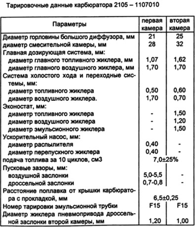
The calibration data of the carburetor 2105-1107010 are shown in the table.
Carburetor 2105-1107010 emulsion type, two-chamber, with a falling stream. The opening of the throttle valve of the first chamber is carried out from the carburetor control pedal in the passenger compartment. The damper of the second chamber opens automatically from the pneumatic actuator. The carburetor has a balanced float chamber, two main dosing systems, a diaphragm starter, an economizer (econostat) pneumatically driven, mechanically driven diaphragm accelerator pump, idle system with first chamber adapter system, second mixing chamber adapter system, positive idle economizer with electronic engine speed control. The carburetor is equipped with a spool-type crankcase ventilation device.
Carburetor 2105-1107010 consists of three body parts: carburetor body 14, carburetor cover 18 and throttle body 13. In the cover 18 there are inlet mouths of the first and second chambers, a well 20 for supplying air to the main air jets 43 and a channel connecting the cavity of the float chamber with the cavity behind the filter element of the air filter.
The air filter housing is installed on four studs screwed into the cover 18. In the inlet neck of the first chamber, an air damper 22 of the starting device is installed. In the cover 18, a needle valve 45 for the fuel supply, a float 48, a fuel filter 46, a branch pipe 47 for supplying fuel to the float chamber are installed. Economizer channels are made in cover 18 (econostat) with emulsion 40, air 41 and fuel 42 jets pressed into the cover. The body 27 of the starting device with the cover 28 and the diaphragm 35, assembled with the rail 26, is attached to the cover 18. The carburetor cover is attached to the body with five screws and sealed with a gasket.
Due to the fact that the float is fixed on the cover of the carburetor body, when it is removed to regulate the fuel level, it is removed from the cavity of the float chamber, while the fuel level changes (in relation to the level on the assembled carburetor). Since direct measurement of the fuel level in the float chamber in mass production turns out to be non-technological, this parameter is not used in the manufacture of carburetors for VAZ engines.
The correctness of setting the fuel level in operation is determined by the size of the gap (6.5±0.25 mm) between the float and the mating surface of the cover, with a gasket installed, while the cover must be installed vertically with the fuel supply pipe 47 upwards, and the float tongue must touch the needle valve ball without sinking it. From the conditions of such regulation, the gasket can be separated from the cover only after the float is removed, which must be borne in mind when dismantling the cover. A similar control system is adopted on carburetors designed by Weber and Solex.
When adjusting the fuel level, you must first make sure that the weight of the float 48 assembly with the lever is 1113 g, the float is not damaged and freely rotates on the axis. To obtain the required clearance, the tongue is bent, which must be perpendicular to the axis of the valve. The float stroke should be 8 mm. If necessary, achieve by bending the stop of the float lever.
In the body 14 of the carburetor, large diffusers are cast, easily removable small diffusers are installed, made integral with the sprayers of the main dosing systems and the sprayer of the econostat. In the housing there are channels of the main dosing systems, an idle system, a transition system, an accelerator pump, a channel 37 for connecting the starting device with the throttle space. In housing 14, a sprayer 39 with an accelerator pump valve, main air jets 43, emulsion tubes 44, housing 58 of the idle fuel jet, housing 17 of the fuel jet of the transition system of the second chamber, main fuel jets 49, air jet 38 of the idle system, bypass jet 51 of the accelerator pump, screw 50 for regulating the fuel supply by the accelerator pump and jets of the pneumatic drive of the throttle valve of the second chamber.
To the tide of the housing, which forms the working cavity of the accelerator pump, the cover of the accelerator pump with the drive lever 54 assembly and the working diaphragm 56 is attached with four screws. A branch pipe 33 is pressed into the body for suction of crankcase gases. An adjusting screw 55 is installed in the tide of the body, which limits the closing of the throttle valve of the first chamber.
In the body 13 of the throttle valves, the shutters of the first and second chambers are installed. On the damper axis of the first chamber are installed: lever 1 of the throttle valve drive from the pedal; lever 5, limiting the opening of the throttle valve of the second chamber, lever 6 of the connection with the air damper, lever 2 of the throttle control (opening starts after the stop of lever 2 selects the gap in the groove of lever 1) and cam 52 of the accelerator pump drive. Under lever 2 in the throttle body, a spring and a crankcase ventilation system spool are installed, access to which opens after unscrewing the nut and removing all levers.
On the axis of the throttle valve 11 there is a lever 9, rigidly fixed on the axis, the lever 8 of the throttle actuator, connected through a spring with the lever 9 and with the rod 7 of the pneumatic actuator diaphragm.
The lever 9 is provided with a protrusion interacting with the finger of the lever 5, which, when the throttle valve of the first chamber is abruptly closed, forces the throttle valve of the second chamber to be forcibly closed due to the action of the return spring.
The forced idle economizer cover with a branch pipe 61 is attached to the body 13 with screws. A diaphragm is installed under the cover, which forms a working cavity located between the cover and the diaphragm. The diaphragm is connected to an economizer needle placed in a seat pressed into body 13.
The idle speed of the engine is regulated by adjusting screws: screw 62 of the amount of the mixture, which regulates the amount of movement of the forced idle economizer needle, and screw 59 of the composition (quality) mixtures. So that the owner does not violate the factory adjustment of the carburetor, restrictive plastic bushings are pressed onto the screws 59 and 62, allowing the screws to be turned only half a turn (idle adjustment). At car service stations, regulation is carried out according to the content of carbon monoxide (SO) in exhaust gases. If the bushings fail to carry out the adjustment, the restrictive bushings are unscrewed, they are broken and the adjustment is carried out with screws 59 and 62. After the adjustment is completed, new restrictive bushings are pressed in. Blue bushings are installed at the car factory, and red bushings are installed at car service stations.