




Open large image in new tab »
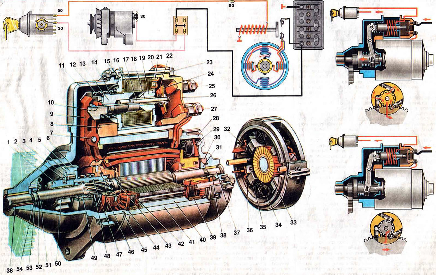
Fig. 32. Starter.
1. Drive gear; 2. Thrust half ring of the overrunning clutch; 3. Overrunning clutch roller; 4. Centering ring of the overrunning clutch; 5. Outer ring of the overrunning clutch; 6. Overrunning clutch housing; 7. Starter gear engagement lever axis; 8. Starter cover sealing plug; 9. Starter gear drive lever; 10. Relay armature thrust; 11. Starter cover on the drive side; 12. Relay anchor return spring; 13. Starter relay anchor; 14. Sliding sleeve; 15. Front relay flange; 16. Relay winding; 17. Anchor rod; 18. Anchor rod sliding sleeve; 19. Relay core; 20. Core flange; 21. Relay winding frame cheek; 22. Armature rod spring; 23. Starter relay tension bolt; 24. Contact plate; 25. Upper contact bolt; 26. Relay cover; 27. Lower contact bolt; 28. Starter cover from the collector side; 29. Inner insulating plate of positive brush holder; 30. Brake disc cover; 31. Anchor shaft brake disc; 32. Starter brush terminal; 33. Collector; 34. Brush spring; 35. Brush holder; 36. Starter brush; 37. Anchor shaft; 38. Starter cover bushing; 39. Shunt coil of the stator winding; 40. Stator pole; 41. Starter housing; 42. Anchor winding; 43. Gear release stroke limiter; 44. Gear travel limiting disk; 45. Leash ring; 46. Centering disc; 47. Overrunning clutch hub; 48. Buffer spring; 49. Overrunning clutch hub insert; 50. Drive gear bushing; 51. Pinion travel limiting ring; 52. Retaining ring; 53. Anchor shaft thrust washer; 54. Axial free play adjusting washer; I. Scheme of operation of the overrunning clutch; II. Starter connection diagram.
1. Drive gear; 2. Thrust half ring of the overrunning clutch; 3. Overrunning clutch roller; 4. Centering ring of the overrunning clutch; 5. Outer ring of the overrunning clutch; 6. Overrunning clutch housing; 7. Starter gear engagement lever axis; 8. Starter cover sealing plug; 9. Starter gear drive lever; 10. Relay armature thrust; 11. Starter cover on the drive side; 12. Relay anchor return spring; 13. Starter relay anchor; 14. Sliding sleeve; 15. Front relay flange; 16. Relay winding; 17. Anchor rod; 18. Anchor rod sliding sleeve; 19. Relay core; 20. Core flange; 21. Relay winding frame cheek; 22. Armature rod spring; 23. Starter relay tension bolt; 24. Contact plate; 25. Upper contact bolt; 26. Relay cover; 27. Lower contact bolt; 28. Starter cover from the collector side; 29. Inner insulating plate of positive brush holder; 30. Brake disc cover; 31. Anchor shaft brake disc; 32. Starter brush terminal; 33. Collector; 34. Brush spring; 35. Brush holder; 36. Starter brush; 37. Anchor shaft; 38. Starter cover bushing; 39. Shunt coil of the stator winding; 40. Stator pole; 41. Starter housing; 42. Anchor winding; 43. Gear release stroke limiter; 44. Gear travel limiting disk; 45. Leash ring; 46. Centering disc; 47. Overrunning clutch hub; 48. Buffer spring; 49. Overrunning clutch hub insert; 50. Drive gear bushing; 51. Pinion travel limiting ring; 52. Retaining ring; 53. Anchor shaft thrust washer; 54. Axial free play adjusting washer; I. Scheme of operation of the overrunning clutch; II. Starter connection diagram.
To start the engine, a ST-221 starter with a power of 1.3 kW is used, with electromagnetic engagement of the drive gear, with a roller overrunning clutch and remote control. Since 1986, an interchangeable starter 35.3708 with a two-winding traction relay and an end collector has been installed on cars.
The ST-221 starter is a four-brush, four-pole DC motor with mixed excitation and consists of a housing 41 with excitation windings, an anchor with a drive, two covers 11 and 28 and a traction electromagnetic relay. The covers and the housing are pulled together into a single unit by two studs screwed into cover 11.
Four poles 40 are fixed with screws inside the steel housing. The winding coils are put on the poles. The housing together with the poles and coils forms the starter stator. Two stator winding coils are series, i.e. connected to the armature winding in series, and the other two are shunt, connected in parallel to the armature winding. Therefore, the excitation of the starter is called mixed. It ensures a relatively low rotation frequency of the armature at idle without load, which reduces wear of the armature shaft bearing bushings, facilitates the operating conditions of the overrunning clutch and prevents the armature from running away.
The starter anchor consists of a shaft 37, a core with a winding 42 made of copper tape and a collector 33 made in the form of a plastic sleeve with copper plates poured into it. The anchor shaft rotates in two metal-ceramic bushings 38 pressed into the starter covers and impregnated with oil. The axial free play of the anchor shaft is adjusted by selecting washers 54 and should be within 0.07-0.7 mm (for starter 35.3708 - no more than 0.5 mm).
The starter drive is mounted on the front end of the armature shaft, consisting of a roller overrunning clutch and gear 1. The purpose of the overrunning clutch is to transmit torque from the starter armature shaft to the flywheel ring gear when starting the engine, and after starting, operating in the overrunning mode, to prevent torque from being transmitted from the flywheel to the armature. Otherwise, the armature winding may be ejected from the core slots due to "runaway" - an excessively high rotation frequency of the armature by the flywheel of the running engine.
The overrunning clutch consists of an outer ring 5 with rollers 3 and an inner ring combined with a drive gear 1. The outer ring has three grooves with holes in which steel rollers with springs, plungers and guide rods are located. The grooves for the rollers are of variable width. In the wide part of the groove, the rollers can rotate freely, and in the narrow part, they are wedged between the outer and inner rings.
The electromagnetic traction relay of the starter serves to engage the drive pinion with the flywheel crown and to close the power supply circuit of the anchor and stator windings. The magnetic system of the relay is formed by flanges 15 and 20, the yoke (surrounding the winding) and a core 19 pressed into a flange 20. The relay coil is wound on a frame made of brass tube and plastic cheeks. Starters manufactured in 1981 have two windings: a holding winding and a pull-in winding. Both windings are wound in the same direction. The beginnings of the windings are soldered to the "50" plug. The end of the holding winding is welded to the relay flange 20 (i.e., connected to the "ground"), and the end of the pull-in winding is connected to the lower contact bolt 27 of the relay.
The 35.3708 starter differs from the ST-221 starter by using an end collector and stator windings. The end collector is made in the form of a plastic disk with copper plates poured into it. Such a collector contributes to more stable and long-term operation of the brush contact, reduces copper consumption, and reduces the weight of the starter. The stator winding consists of three series and one shunt coil, which increased the anchor torque. Otherwise, the design of the 35.3708 starter is the same as that of the ST-221 starter.
Starter operation
When the key is turned to position II ("Starter"), contacts "30" and "50" of the ignition switch close, and current begins to flow through the windings of the traction relay.
Under the action of this current, a magnetic force of about 10-12 kgf arises, pulling the relay anchor until it touches core 19. In this case, the contact plate closes contacts 25 and 27.
In a starter with a two-winding traction relay, when the contact bolts are closed, the pull-in winding is de-energized, since both its ends are connected to the "plus" of the storage battery. Since the anchor is already pulled into the relay, then to hold the anchor in this position, a relatively small magnetic flux is required, which is provided by one holding winding.
Moving, the relay anchor through the lever 9 moves the overrunning clutch with the gear. The hub of the overrunning clutch, turning on the screw splines of the starter anchor shaft, also turns the gear 1, which facilitates its engagement with the flywheel ring. In addition, the chamfers on the side edges of the teeth of the gear and the flywheel ring, as well as the buffer spring, transmitting the force from the lever 9 to the hub 47 of the clutch, facilitate the engagement of the gear and soften the impact of the gear on the flywheel ring.
The supply current of the stator and anchor goes through the closed contacts of the relay. The anchor of the starter starts to rotate together with the hub 47 and the outer ring of the overrunning clutch. Since the clutch rollers are displaced by springs into the narrow part of the groove of the outer ring, and the gear is braked by the flywheel ring, the rollers are wedged between the rings of the overrunning clutch, and the torque from the anchor shaft is transmitted through the clutch and gear to the flywheel ring.
After the engine starts, the rotation speed of the pinion begins to exceed the rotation speed of the starter anchor. Inner ring of the overrunning clutch (combined with gear) draws the rollers into the wide part of the groove of the outer ring 5, compressing the plunger springs. In this part of the groove, the rollers rotate freely without jamming, and the torque from the engine flywheel is not transmitted to the starter anchor shaft.
After the key is returned to position I ("Ignition"), the power supply circuit of the traction relay windings is opened. The relay anchor under the action of spring 12 returns to its original position, opening contacts 25 and 27 and returning the overrunning clutch with the gear to its original position. Spring 12 through the lever, disk 44 and limiter 43 presses on the anchor towards cover 28. Steel brake disk 31 of the anchor shaft rests against brake disk 30 of the cover, and the anchor quickly stops rotating. In starter 35.3708, anchor braking occurs due to the friction of the brushes on the collector.