




Removal
1. Place the vehicle on an inspection pit or overpass (see "Preparing a car for maintenance and repair").
2. Remove the cylinder head from the engine (see "Cylinder Head Gasket - Replacement").
3. Remove the engine oil pan (see "Engine oil pan - removal and installation").
4. Unscrew the connecting rod cap nuts (without removing the crankshaft) and push the piston with the connecting rod out of the cylinder block (see "Crankshaft - removal and installation").
5. Remove the steel-aluminum insert from the connecting rod cap.
The connecting rod and cover are stamped with the number of the cylinder into which they are installed.
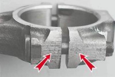
6. Place the connecting rod in a vice and remove two compression rings and one oil scraper ring with an expander from the piston.
7. Using a mandrel, press the pin out of the connecting rod and remove the piston.
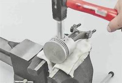
We remove the pistons of the remaining cylinders in the same way.
Before installing the piston group on the connecting rod, its parts must be selected.
Selection of connecting rod and piston group parts
1. Select a piston for the cylinder. The calculated gap between the cylinder and the engine piston should be 0.06-0.08 mm. It is determined by measuring the cylinders and pistons and is ensured by installing pistons of the same class as the cylinders. The maximum allowable gap is 0.15 mm. The piston diameter is measured in a plane perpendicular to the piston pin, at a distance of 52.4 mm from the piston bottom. Pistons are made in five classes according to the outer diameter (A, B, C, D and E) through 0.01 mm, and by the diameter of the hole for the piston pin - three categories through 0.004 mm. Pistons of groups A, C and E are supplied as spare parts. The piston class (letter) and the category of the hole for the piston pin (number) are stamped on the piston bottom.
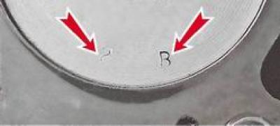
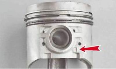
For correct orientation of the piston relative to the cylinder on the piston wall (next to the boss) the "P" mark is made and should be directed towards the front of the cylinder block.
We measure the cylinder diameter with a bore gauge in four zones, both in the longitudinal and transverse directions of the engine.
In the zone of belt 1, the cylinders practically do not wear out. Therefore, by the difference in measurements in the first and other belts, we judge the amount of wear of the cylinders.
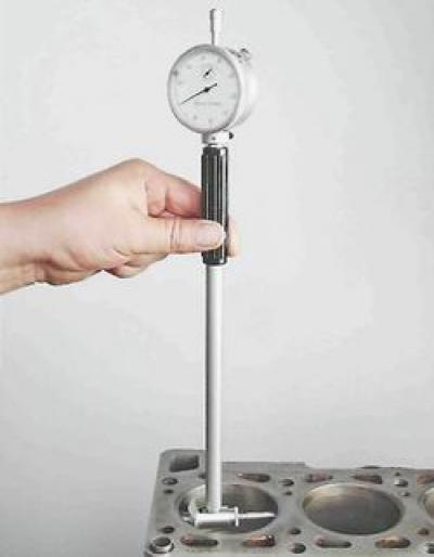
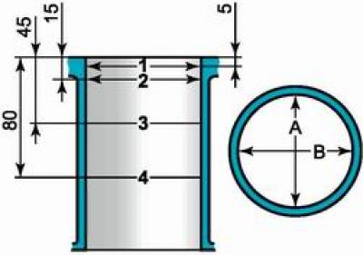
Diagram of measuring cylinder diameters: 1, 2, 3 and 4 - belt numbers; A and B are the directions of measurements
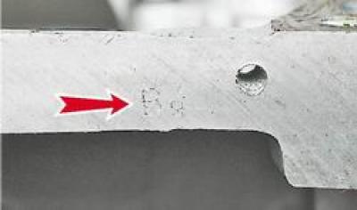
The cylinders are divided by diameter into five classes, 0.01 mm apart: A, B, C, D and E. The cylinder class is stamped on the lower plane of the block.
2. Select the pin for the piston. The pin is installed in the upper head of the connecting rod with tension and rotates freely in the cylinder bosses. According to the outer diameter, the pins are divided into three categories through 0.004 mm. The categories are indicated by a color mark on the end of the pin: blue - first category, green - second, red - third. We check the mating of the piston pin and the piston by inserting the piston pin (lubricated with motor oil) into the piston boss holes. The piston pin should be installed by simply pressing the thumb and should not fall out when the finger is in a vertical position.
3. Check the clearance between the grooves and the piston rings. The clearances must correspond to the values given in Table 8.1.3 (see below). An increased clearance leads to rapid wear (breaking) piston grooves.
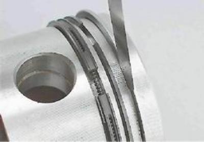
Table 8.1.2. Dimensions of the main mating parts of the engine
|
Mating parts |
Dimensions of parts, mm |
Acceptable |
||
|
Shaft |
Hole |
|||
|
Piston - cylinder (for VAZ-2103 engine) |
Class A |
75,94-75,95 |
76,00-76,01 |
0,15 |
|
Class B |
75,95-75,96 |
76,01-76,02 |
||
|
Class C |
75,96-75,97 |
76,02-76,03 |
||
|
Class D |
75,97-75,98 |
76,03-76,04 |
||
|
Class E |
75,98-75,99 |
76,04-76,05 |
||
|
Piston - cylinder (for engines VAZ-2106, VAZ-21011) |
Class A |
78,94-78,95 |
79,00-79,01 |
0,15 |
|
Class B |
78,95-78,96 |
79,01-79,02 |
||
|
Class C |
78,96-78,97 |
79,02-79,03 |
||
|
Class D |
78,97-78,98 |
79,03-79,04 |
||
|
Class E |
78,98-78,99 |
79,04-79,05 |
||
|
Piston pin - piston |
1st category (blue mark) |
21,970-21,974 |
21,982-21,986 |
- |
|
2nd category (green mark) |
21,974-21,978 |
21,986-21,990 |
||
|
3rd category (red mark) |
21,978-21,982 |
21,990-21,994 |
||
|
Piston pin - upper head of the connecting rod |
21,970-21,982 |
21,940-21,960 |
- |
|
Table 8.1.3. Clearances in the mating grooves and piston rings
|
Mating parts |
Dimensions of parts, mm |
Acceptable |
|
|
Ring height |
Groove width |
||
|
Upper compression ring - piston groove |
1,478-1,490 |
1,535-1,555 |
0,15 |
|
Lower compression ring - piston groove |
1,978-1,990 |
2,015-2,035 |
0,15 |
|
Oil scraper ring - piston groove |
3,925-3,937 |
3,957-3,977 |
0,15 |
Table 8.1.4. Piston ring gaps
|
Name of the ring |
Gap size, mm |
|
Upper compression ring |
0,30-0,45 |
|
Lower compression ring |
0,25-0,40 |
|
Oil scraper ring |
0,25-0,40 |
Assembly of the connecting rod and piston group
1. Place finger 4 on mandrel 2 without tightening stop 3 too much.

2. Cool the connecting rod pin in a freezer. Heat the upper head of the connecting rod to 240°C with a blowtorch or industrial hair dryer, clamp the connecting rod in a vice and put the piston on it (the "P" mark on the piston should be on the side of the oil outlet hole on the lower head of the connecting rod).
3. Push the pin installed on the mandrel into the holes of the piston bosses and the upper head of the connecting rod until the ring belt 1 on the handle stops in the piston.
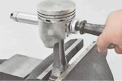
4. After the connecting rod has cooled, lubricate the pin with engine oil through three holes in each piston boss and through the gap between the boss and the connecting rod.
5. Lubricate the piston rings and grooves with engine oil. Install the rings on the piston and orient the ring locks. The lock of the upper compression ring should be located at an angle of 30-45° to the axis of the piston pin, the lock of the lower compression ring should be directed in the opposite direction, and the lock of the oil scraper ring - at an angle of 30-45° to the axis of the piston pin between the locks of the compression rings. Install the lower compression ring with the groove down. If the ring has a mark "TOP" or "TOR", it should be directed towards the piston bottom. The joint of the spring expander of the oil scraper ring should be located on the side opposite the ring lock.
6. After installing the rings, install the crankshaft according to the mark (pistons of cylinders 1 and 4 must be in BMT) and alternately insert the pistons with rings and connecting rods into the 2nd and 3rd cylinders. In this case, the "P" marks on the pistons should be directed towards the front part of the cylinder block. To compress the rings, it is recommended to use the mandrel shown in the photo.
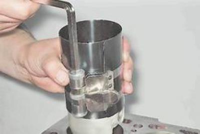
After this, we install the connecting rod bearings in place, having previously lubricated them and the crankshaft journals with engine oil, and connect the connecting rods to the crankshaft journals. We install the covers according to the marks and tighten the nuts with a torque of 43.4-53.5 Nm. Having turned the crankshaft by 180°, we connect the connecting rods of the 1st and 4th cylinders to the crankshaft. We check the ease of rotation of the crankshaft.
7. Installation of the remaining removed parts is carried out in the reverse order.
8. Fill the engine with engine oil (see "Engine Oil - Checking Level and Replacement").
10. Adjust the chain tension (see "Timing Chain - Replacement").
11. Adjust the clearance between the levers and the camshaft cams (see "Clearance between valve levers and camshaft cams - adjustment"). We check the free rotation of the crank mechanism.
12. Adjust the tension of the generator drive belt (see "Generator Drive Belt - Tension Adjustment and Replacement").
13. On a carburetor engine, check and, if necessary, adjust the ignition timing angle (see "Ignition timing - checking and adjustment").
14. Fill the system with coolant (see "Coolant - Checking Level and Replacing").
15. Start the engine and run it in at idle for 20-30 minutes, gradually increasing the crankshaft speed to 2000 rpm. While the engine is running, check the tightness of the engine systems, oil pressure, and coolant temperature. If extraneous noises are detected during engine operation, stop the engine to eliminate the causes of their occurrence.