
Rear suspension elements
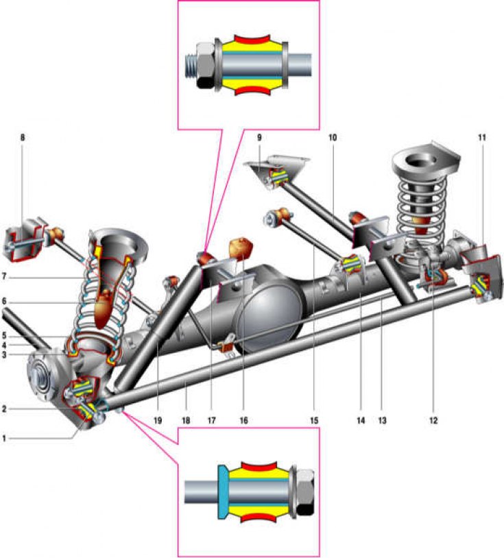
1 - spacer sleeve; 2 - rubber bushing; 3 - the lower insulating gasket of the spring; 4 - lower longitudinal rod; 5 - the lower support cup of the spring; 6 – compression stroke buffer; 7 - suspension spring; 8 – a bolt of fastening of the top longitudinal bar; 9 – an arm of fastening of the top longitudinal bar; 10 - lower longitudinal rod; 11 - cross bar bracket; 12 - pressure regulator; 13 – pressure regulator drive lever; 14 - rear axle beam; 15 - upper longitudinal rod; 16 - additional compression stroke buffer; 17 - shock absorber bracket; 18 - transverse rod; 19 - shock absorber.
Design Description
Rear suspension - dependent with coil springs and hydraulic shock absorbers.
The rear axle beam is fixed to the body with four longitudinal (reactive) and one transverse rod on rubber-metal hinges of the same design (silent blocks).
The springs rest with their lower ends through plastic gaskets into cups welded to the rear axle beam, and with their upper ends through rubber anti-vibration gaskets into the body. The compression stroke of the springs is limited by cylindrical stops, which are part of the car body. Rubber buffers are installed at the ends of the stops.
An additional compression buffer is mounted on a bracket above the gearbox housing.
The shock absorbers are mounted on collapsible rubber-metal hinges - with the upper lugs to the studs on the body brackets, and the lower ones - to the brackets on the rear axle beam.