




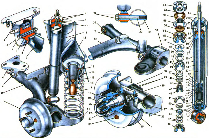
1. Brake drum with rear wheel hub. 2. Rear suspension arm. 3. Suspension arm mounting bolt. 4. Suspension arm mounting bracket. 5. Rubber bushing of arm joint. 6. Expansion sleeve of arm joint. 7. Body side member. 8. Shock absorber mounting washer. 9. Expansion sleeve. 10. Shock absorber mounting cushion. 11. Rear suspension shock absorber. 12. Upper support cup of suspension spring. 13. Suspension spring insulating gasket. 14. Compression buffer cage strut. 15. Rear suspension spring. 16. Compression buffer cage. 17. Compression buffer. 18. Rear wheel hub bearings. 19. Thrust washer. 20. Adjusting nut. 21. Suspension arm bracket. 22. Cotter pin. 23. Wheel hub cap. 24. Plug. 25. Wheel hub oil seal. 28. Brake support shield. 27. Wheel hub axle mounting bolt. 28. Wheel axle. 29. Mud deflector rings. 30. Suspension arm flange. 31. Suspension arm bushing. 32. Shock absorber mounting bolt. 33. Rubber-to-metal joint of shock absorber head. 34. Rubber-to-metal joint of suspension arm. 35. Arm connector. 36. Compression valve housing. 37. Compression valve discs. 38. Compression valve throttle disc. 39. Compression valve plate. 40. Compression valve spring. 41. Compression valve housing. 42. Rebound valve nut. 43. Rebound valve spring. 44. Shock absorber piston. 45. Rebound valve plate. 46. Rebound valve nut washer. 47. Rebound valve discs. 48. Piston ring. 49. Rebound valve throttle disc. 50. Bypass valve plate. 51. Bypass valve spring. 52. Bypass valve limiting plate. 53. Shock absorber rod. 54. Cylinder. 55. Reservoir. 56. Protective cover. 57. Rod guide sleeve. 58. Reservoir sealing ring. 59. Rod seal collar. 60. Rod seal. 61. Rod protective ring gasket. 62. Protective ring of the rod. 63. Reservoir nut. 64. Housing cover. 65. Spacer sleeve.
The rear suspension is of the torsion-lever type, independent. It consists of a guide device, elastic and damping elements. The guide device is formed by two levers 2, connected to each other by an elastic connector 35 of a U-shaped cross-section. The connector of the levers, rigid in bending and flexible in torsion, is located in front of the wheels, approximately 1/3 of the length of the lever from the axes of their swing. With such an arrangement of the connector, each wheel has independent movement of the wheels from each other, accompanied by elastic twisting of the connector of the levers.
The rear suspension arms 2 are made of electric-welded pipes. They are welded to the connector via arm reinforcements and form, together with the connector, a single beam pivotally suspended on brackets 4 to the body. Each suspension arm has a bushing at the front, into which a rubber-metal hinge 34 is pressed, consisting of a rubber 5 and metal 6 bushings. Bolts 3 pass through the spacer bushings 6 of the hinges, connecting the suspension arms with stamped brackets 4, the left of which is fastened to the body side member 7 with bolts, and the right is welded to the side member. Nuts with spring washers are screwed onto the arm fastening bolts.
Brackets 21 are welded to the rear of the levers, on which the springs rest. Flanges 30 with threaded holes for bolting the axle 28 of the rear wheel hub to the suspension arm are welded to these brackets. At the front of the brackets, spacer bushings 31 with threads for console mounting of the lower ends of the shock absorbers are entrusted to the arm tube. In addition, brackets for fastening the tips of the brake hoses and the casing of the rear parking brake cable are welded to the suspension arms.
The elastic elements of the suspension consist of a spring 15 and a buffer 17 of the compression stroke. The spring is twisted, cylindrical, made of spring steel of a round cross-section. It is installed under the floor of the body: the lower part rests on the bracket 21 of the suspension arm, and the upper part - through the rubber insulating gasket 13 in the upper support 12, welded to the wheel arch and to the floor of the body.
Springs are divided into two classes according to their length under test load: A and B. Class A springs are marked with yellow paint on the outer side of the middle coils, and class B springs are marked with green paint.
The rubber compression buffer is installed inside the spring. It is secured with its mushroom-shaped nipple in the opening of the collar 16, which is welded to the pillar 14 of the buffer support, and the pillar, in turn, to the upper support of the suspension spring. When switched on, the compression buffer rests against the platform of the lever bracket
The axle 28 of the rear wheel is attached to the flange 30 of the suspension arm with three bolts. The shield 26 of the brake mechanism is attached together with the axle with the same bolts. The brake drum 1, made integral with the hub of the rear wheel, rotates on the axle on two tapered roller bearings 18. The brake drum is attached to the axle with a crown nut 20 with a thrust washer 19. The nut is fixed on the axle with a cotter pin 22. The wheel hub bearings are sealed on the inside of the drum with an oil seal 25 and two mud-deflecting rings 29, one of which is welded to the flange of the wheel axle, and the other to the brake drum. The outer mud-deflecting ring enters the annular groove of the flange of the axle. In this way, a labyrinth seal is created to protect the oil seal. From the outer end of the drum, the bearing cavity is sealed with a cap 23, pressed into the wheel hub socket.
The clearance in the rear wheel hub bearings is adjusted with a crown nut. It should be within 0.02...0.13 mm and should not exceed 0.20 mm. The wheel disk is attached to the brake drum with three nuts.
Shock absorber 11 of the rear suspension is hydraulic, telescopic, double-acting. It is unified with the shock absorber of the car VAZ-2101, except for the length dimensions, valve calibration parameters and protective casing. The lower head of the shock absorber is mounted console-style on the bushing 31 of the suspension arm with a bolt.
The upper part of the shock absorber is attached by a rod through rubber cushions 10 to a bracket welded to the rear wheel arch. A thrust washer 8 is installed between the self-locking nut and the upper rubber cushion, and a spacer sleeve 9 is installed between the casing cover 64 and the washer. To prevent the rod from turning when tightening the nut, the rod has flats for a key.
The shock absorber consists of a reservoir 55, a cylinder 54, a compression valve, a rod 53 assembled with a piston 44 and valves, a guide sleeve 57 and sealing and fastening parts.
Tank 55 is made from a pipe, to the lower part of which a bottom with a lower eye is welded, and in the upper part an internal thread is cut for nut 63.
The compression valve is pressed into the lower part of the cylinder and pressed by it to the bottom of the reservoir when tightening nut 63. It consists of body 36, collar 41, plate 39, pack of disks 37 and 38 and spring 40. The body has a central seat, to the chamfer of which the compression valve disks are pressed from above. Cross-shaped cutouts for the passage of liquid are made in the upper and lower parts of the body. The disk pack consists of three flat disks, one of which (pos. 38) has a cutout for throttling the liquid. It is located in the upper part of the pack. The disks are pressed to the chamfer of the seat by spring 40 through plate 39, which has four through holes for the passage of liquid and a cylindrical protrusion. This protrusion presses the plate to the edge of the inner hole of the throttle disk. Due to the cylindrical belt between the outer edges of the throttle disk and the plate, a gap is formed along the entire perimeter for the passage of liquid to the throttle cutout of the disk. The sleeve 41 is pressed onto the valve body from above. It has a seating belt with a flange for seating in the opening of the cylinder 54. One central and six radial openings for the passage of liquid.
In cylinder 54, rod 53 moves in assembly with piston 44 and two valves - bypass and return. The movement of the rod in the cylinder is directed by metal-ceramic bushing 57. It is pressed into the upper part of the cylinder. A channel is made in the bushing for draining liquid from the annular cavity of the bushing into the cavity of the reservoir so that liquid pressure is not created on the gland 60. Liquid enters the annular cavity of the bushing through the gap between the guide bushing and the rod. The bushing is sealed in the reservoir by rubber ring 58, which is pressed to the collar of the bushing and to the surface of the reservoir by gland collar 59. The same collar presses gland 60, the working edges of which cover the chromed surface of the rod, to the guide bushing. So that during suspension movements the gland is not damaged by various deposits on the rod (ice, dirt, etc.), a mud-deflecting ring 62 is installed, which removes these deposits from the rod. A rubber gasket 61 is clamped between the ring and the gland housing, insulating them.
The nut is supported on top by a protective cover 64 made of plastic. It protects the rod from contamination and mechanical damage. The upper end of the rod has a flat for a key to hold the rod from turning when removing or installing it.
The following are installed in the lower part of the rod: a limiting plate 52 of the bypass valve, a flat spring 51 and a plate 50 of the bypass valve, a piston 44 with a sealing ring 48, discs of the recoil valve, a thrust plate 45, a spring 43 of the recoil valve and a nut 42 is screwed on. It is fixed by punching the end of the rod.
The piston is metal-ceramic and has vertical channels located along two radii. The channels of each circle are connected to each other by an annular groove. The channels located closer to the center of the piston are blocked from below by the discs of the recoil valve (pos 47 and 49), and at the top - further from the center - by plate 50 of the bypass valve, pressed by spring 51. The movement of the plate is limited by the spring stopping at plate 52. The piston is sealed in the cylinder by ring 48.
The discs of the recoil valve are pressed to the lower end part of the piston by spring 43 through plate 45. In this case, the spring presses the outer part of the discs, and the inner part of the discs 47 is tightly pressed to the piston by nut 42 screwed onto the threaded end of the rod. To protect the discs of the recoil valve from damage and to stabilize the operation of the valve, a washer 46 is installed between the discs and the nut.
The throttle disc 49 of the recoil valve has four cutouts on the outer diameter for the passage of fluid during smooth recoil.
The working process of the shock absorber is similar to the work of the front suspension strut.
(The information is published on the website: vazbook)