




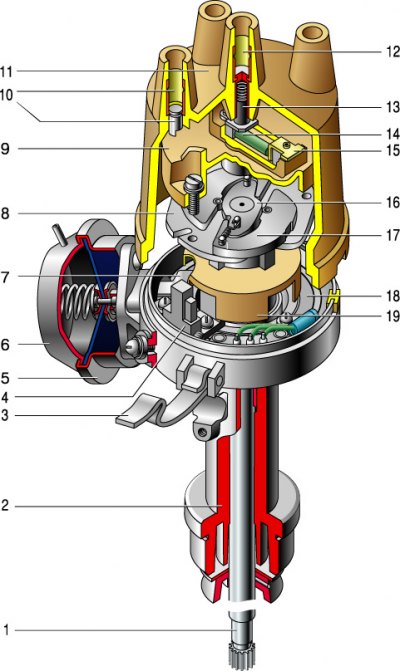
1 – roller; 2 – ignition distributor sensor housing; 3 – lid locking spring; 4 – contactless sensor; 5 – vacuum regulator housing; 6 – diaphragm; 7 – vacuum regulator rod; 8 – centrifugal regulator support plate; 9 – ignition distributor rotor; 10 – side electrode with terminal; 11 – lid; 12 – central electrode with terminal; 13 – central electrode carbon; 14 – resistor; 15 – outer rotor contact; 16 – leading plate of the centrifugal regulator; 17 – centrifugal ignition timing regulator weight; 18 – contactless sensor support plate; 19 – screen.
The ignition distributor sensor is a four-spark one, with a contactless control pulse sensor and built-in vacuum and centrifugal ignition advance regulators.
The ignition distributor sensor transmits control signals to the switch, setting the moment of spark formation, and distributes high-voltage current pulses to the spark plugs.
The sensor is installed in the front part of the cylinder block on the left side.
The housing of the sensor-distributor is cast from an aluminum alloy. Two plain bearings in which the roller rotates are pressed into the housing tail. A screen is fixed on the roller. When the roller rotates, the teeth of the screen pass through the slot of the contactless sensor, creating control pulses in the sensor's electrical circuit. A centrifugal regulator is mounted in the upper part of the roller, on the support plate of which the rotor (runner) is fixed. When the roller rotates, the weights of the centrifugal regulator diverge under the action of centrifugal forces, turning the screen at a certain angle in the direction of rotation of the roller. Control pulses are created with an advance, which is greater, the faster the rotation. The angle of rotation is limited by the size of the groove in the support plate of the centrifugal regulator.
The contactless sensor support plate is mounted on a ball bearing, which allows it to rotate around the shaft axis. The plate is connected by a rod to the diaphragm of the vacuum ignition advance regulator. Vacuum (supplied through a hose from the carburetor throttle body) acts on the diaphragm of the vacuum regulator, and the rod rotates the support plate together with the sensor relative to the screen, thereby ensuring the optimal ignition timing depending on the engine load.
The top of the distributor sensor housing is covered with a cover with sockets for high-voltage wires. On the inside of the cover, a spring-loaded carbon is mounted in its central electrode. The rotor with a contact plate (runner) distributes high-voltage current to the spark plugs in accordance with the firing order of the cylinders (1–3–4–2). The shaft of the distributor sensor rotates clockwise when viewed from above.
Distributor 30.3706 and distributor sensor 38.3706 are identical in terms of mounting locations and method of fastening on the engine, and their covers and rotors (runners) are interchangeable.
Switch 3620.3734
The switch converts the control pulses of the contactless sensor into a pulse current supplied to the primary winding of the ignition coil. The serviceability of the switch cannot be checked without special equipment.
[The text is copied from the online portal: vazbook.ru]
Caution! To avoid damaging the switch, do not disconnect its connector when the ignition is on; do not remove the battery terminals when the engine is running. Regularly check the reliability of the commutator ground connection to the body.
Otherwise, the contactless system is similar to the contact ignition system.