
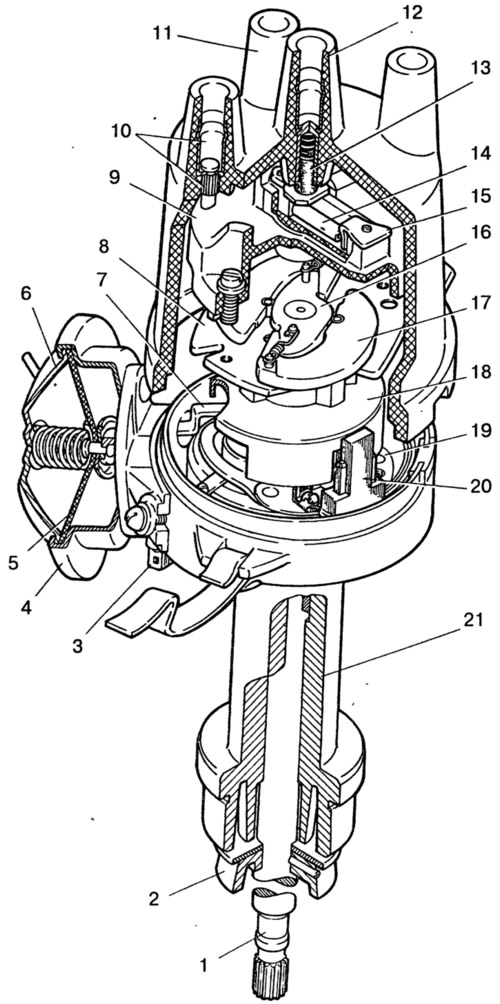
Pic. 7-19. Sensor-distributor ignition 3810.3706:
1 - roller; 2 - oil slinger; 3 - plug connector; 4 - housing of the vacuum regulator; 5 - diaphragm; 6 - vacuum regulator cover; 7 - thrust of the vacuum regulator; 8 - base plate of the centrifugal regulator; 9 - ignition distributor rotor; 10 - side electrode with terminal; 11 - cover; 12 - central electrode with terminal; 13 - coal of the central electrode; 14, - resistor; 15 - outer contact of the rotor; 16 - centrifugal regulator plate; 17 - weight; 18 - screen; 19 - contactless sensor support plate; 20 - proximity sensor; 21 - ignition distributor sensor housing.
Checking work
Install the ignition distributor on the electrical test bench and connect it to the variable speed motor.
Connect the outputs of the ignition distributor sensor to the ignition coil, to the switch and to the battery of the stand in the same way as the car ignition system diagram. Connect the four terminals of the cover to spark gaps, the gap between the electrodes of which is adjustable.
Set a gap of 5 mm between the electrodes of the arresters, turn on the electric motor of the stand and rotate the roller of the sensor-distributor for several minutes clockwise at a frequency of 2000 min-1. Then increase the gap between the electrodes to 10 mm and watch for internal discharges in the distribution sensor. They are detected by sound or by the weakening and interruption of sparking on the arrester of the test bench.
During operation, the ignition distribution sensor should not produce noise at any roller speed.
Removing the characteristics of automatic ignition advance
Install the ignition distribution sensor on the stand, connect its leads to the leads «3», «5» and «6» switch 1 (pic. 7-20) stand. Conclusion «4» connect the switch to the terminal «plus» stand, and output «1» - with terminal «breaker» stand. Set a gap of 7 mm between the spark gap electrodes.
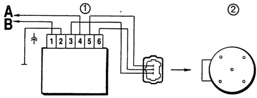
Pic. 7-20. Scheme for characterization of the ignition distributor sensor on the stand:
1 - switch; 2 - sensor-distributor ignition; A - to the terminal «plus» stand; B - to terminal «breaker» stand.
Turn on the electric motor of the stand and rotate the shaft of the ignition distributor with a frequency of 500-600 min-1. On the graduated disk of the stand, note the value in degrees at which one of the four sparks is observed.
Increasing the speed in steps by 200-300 min-1, determine from the disk the number of degrees of ignition advance corresponding to the rotational speed of the ignition distributor shaft. Compare the obtained characteristic of the centrifugal ignition timing controller with the characteristic in fig. 7-21.
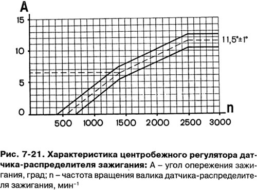
If the characteristic differs from that shown in Fig. 7-21, then it can be brought back to normal by bending the spring racks of the weights of the centrifugal regulator. Up to 1500 min-1 - bend the rack of a thin spring, and over 1500 min-1 - thick. To decrease the angle, increase the tension of the springs, and to increase, decrease.
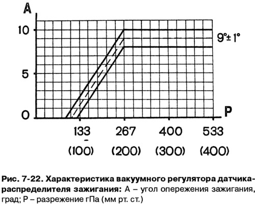
To measure the characteristics of the vacuum regulator of the ignition timing, connect the fitting of the vacuum regulator to the vacuum pump of the stand.
Turn on the electric motor of the stand and rotate the shaft of the ignition distributor with a frequency of 1000 min-1. On the graduated disk, note the value in degrees at which one of the four sparks occurs.
Gradually increasing the vacuum, every 26.7 hPa (20 mmHg Art.) note the number of degrees of ignition advance relative to the original value. Compare the resulting characteristic with the characteristic in Fig. 7-22.
Pay attention to the clarity of the return to its original position after removing the vacuum of the plate on which the proximity sensor is attached.
Checking the proximity sensor
Voltage is removed from the sensor output if there is a steel screen in its gap. If there is no screen in the gap, then the voltage at the output of the sensor is close to zero.
On the sensor-distributor of ignition removed from the engine, the sensor can be checked according to the diagram shown in fig. 7-23, with a supply voltage of 8-14 V.
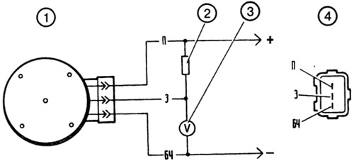
Pic. 7-23. Scheme for checking the proximity sensor on the removed ignition distributor sensor:
1 - sensor-distributor ignition; 2 - resistor 2 kOhm; 3 - voltmeter with a scale limit of at least 15 V and an internal resistance of at least 100 kOhm; 4 - view of the plug connector of the ignition distributor.
Slowly rotating the ignition distributor shaft, measure the voltage at the sensor output with a voltmeter. It should change sharply from the minimum - no more than 0.4 V, to the maximum - no more than 3 V lower supply voltage.
On the car, the sensor can be checked according to the diagram shown in fig. 7-24. Between the plug connector of the ignition distributor and the connector of the wiring harness, an adapter connector 2 with a voltmeter is connected. Turn on the ignition and, slowly turning the crankshaft with a special key, check the voltage at the sensor output with a voltmeter. It must be within the above limits.
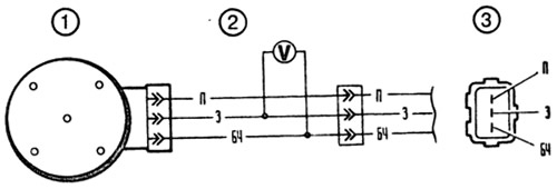
Pic. 7-24. Scheme for testing a proximity sensor on a car:
1 - sensor-distributor ignition; 2 - adapter with a voltmeter having a scale limit of at least 15 V and an internal resistance of at least 100 kOhm; 3 - view of the plug connector of the ignition distributor.