
Ignition distributor 38.3706-01
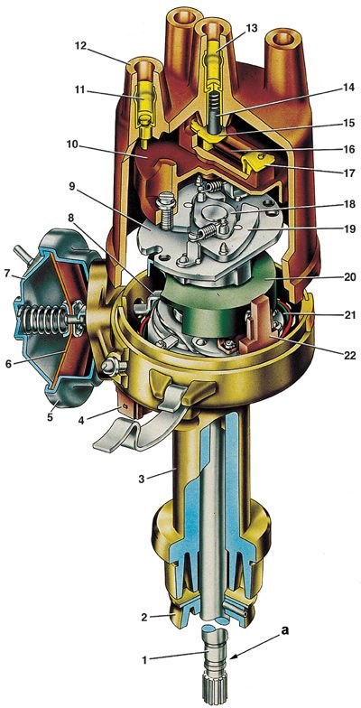
1 - roller of the sensor-distributor of ignition; 2 - oil-slinging sleeve of the roller; 3 - housing of the sensor-distributor; 4 - plug connector; 5 - housing of the vacuum regulator; 6 - diaphragm; 7 - vacuum regulator cover; 8 – draft of the vacuum regulator; 9 - support (driven) ignition timing regulator plate; 10 – ignition distributor rotor; 11 - side electrode with a terminal for a wire to a spark plug; 12 – a cover of the distributor of ignition; 13 - central electrode with a terminal for wire from the ignition coil; 14 - coal of the central electrode; 15 – central contact of the rotor; 16 - 1000 Ohm resistor for suppressing radio interference; 17 - outer contact of the rotor; 18 - leading plate of the centrifugal regulator; 19 - weight of the ignition timing regulator; 20 - screen; 21 - mobile (support) non-contact sensor plate; 22 - proximity sensor; a - a groove for distinguishing sensors-distributors 38.3706
Attention! On cars with a contactless ignition system, the ignition distributor sensor 38.3706-01 is used (see fig. Ignition distributor 38.3706-01).
Contacts must be in contact with the entire surface. If this does not happen, then bending the rack bracket, adjust the position of the fixed contact. It is impossible to bend the lever with a movable contact.
Checking work
1. Before installing the ignition distributor on the stand, check the condition of the breaker contacts, whether the lever with the moving contact is sticking on the axis and the pressing force of the contacts, which should be 4.9–5.88 N (500–600 gs).
2. Check the wear of the textolite block of the breaker lever. In case of wear, set the required gap between the breaker contacts. If the lever sticks on the axis or its spring is weakened, replace the contact group.
3. If the breaker contacts are dirty, burnt, or eroded, clean them with a velvet file. Grinding paper and other abrasive materials cannot be used for this purpose.
4. After stripping, wipe the breaker contacts with chamois soaked in gasoline.
5. Then pull back on the lever to let the gasoline evaporate, and wipe the contacts again with dry chamois leather. Instead of suede, you can use any material that does not leave fibers.
6. Wipe off the ignition distributor cap from dirt and oil.
7. Slightly lifting the cover of the ignition distributor, check whether the outer contact of the rotor is against the electrode of the cover at the moment the breaker contacts open.
8. Install distributor (or distribution sensor) to a test bench for testing electrical ignition devices and connect it to an electric motor whose speed is adjustable.
9. Make connections to the ignition coil, battery and switch (for sensor-distributor 38.3706-01) similar to the car ignition system. Connect the four terminals on the cover on the stand with spark gaps, the gap between the electrodes of which is adjustable.
10. Set a gap of 5 mm between the electrodes of the arresters, turn on the electric motor of the stand and rotate the ignition distributor shaft for several minutes clockwise at a frequency of 2000 min–1.
11. Then increase the gap between the electrodes to 10 mm and watch for internal discharges in the distributor. They are detected by sound or by the weakening and interruption of sparking on the arrester of the test bench.
12. During operation, the ignition distributor must not produce noise at any speed of the roller.
Removing the characteristics of automatic ignition advance
Scheme for characterization of the ignition distributor sensor on the stand
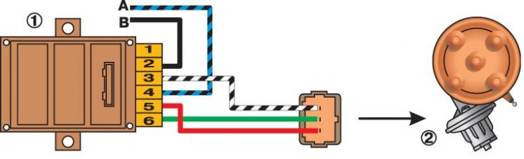
1 - switch; 2 - sensor-distributor ignition; A - to the terminal "+" stand; B - to the terminal "breaker" booth
Characteristics of centrifugal (A) and vacuum (b) ignition timing regulators
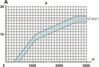
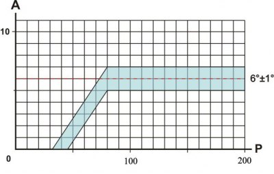
А – ignition advance angle, deg;
n - rotational speed of the ignition distributor roller, min-1;
P - rarefaction, mm Hg. Art.
1. Install the ignition distributor (or distribution sensor) to the stand and make electrical connections in accordance with the instructions for the stand.
2. For the ignition distributor sensor 38.3706-01, make the connections according to the diagram in fig. Scheme for characterization of the ignition distributor sensor on the stand. Set a gap of 7 mm between the spark gap electrodes.
3. Turn on the electric motor of the stand and rotate the ignition distributor roller at a frequency of 150–200 min–1. On the graduated disk of the stand, note the value in degrees at which one of the four sparks is observed.
4. Increasing the speed in steps by 200–300 min–1, determine from the disk the number of degrees of ignition advance corresponding to the rotational speed of the ignition distributor shaft. Compare the obtained characteristic of the centrifugal ignition timing regulator with the characteristic in Fig. Characteristics of centrifugal (A) and vacuum (b) ignition timing regulators, a.
Checking the angle of the closed state of the contacts
1. Turn on the electric motor of the stand and bring the rotational speed of the ignition distributor roller to 1000 min–1.
2. On the illuminated parts of the scale, measure the angle of the closed state of the contacts, which should be 55±3°.
3. Then check the angles between the opening moments of the contacts on the cylinders relative to the first (asynchronism), which should not differ from the nominal by more than±1°.
Removal of characteristics of the vacuum regulator
1. Connect the vacuum regulator of the ignition distributor with the vacuum pump of the stand with a hose.
2. Turn on the electric motor of the stand and rotate the ignition distributor shaft with a frequency of 1000 min–1.
3. According to the graduated disk, set the conditional "zero" by the moment of sparking in any of the cylinders.
4. Gradually increasing the vacuum, every 20 mm Hg. Art. note the number of degrees of ignition advance relative to the original value. Compare the resulting characteristic with the characteristic in Fig. Characteristics of centrifugal (A) and vacuum (b) ignition timing regulators, b.
5. Pay attention to the clarity of the return to its original position after removing the vacuum of the moving plate 26 (see fig. Ignition distributor 30.3706-01) breaker.
Insulation resistance test
1. The insulation resistance between the high-voltage terminals and ground is checked with a megohmmeter and must be at least 10 ohms at (25±5) °C.
2. The resistance between the low voltage terminal of the breaker and ground should be the same. It is measured with the breaker contacts open.
Capacitor check
Capacitor capacitance, measured in the frequency range between 50 and 1000 Hz, should be in the range of 0.20-0.25 µF.
Checking the proximity sensor in the ignition distributor 38.3706-01
Schemes for testing a proximity sensor on a car (A) and on the removed ignition distributor (b)
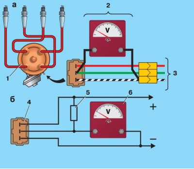
1 - sensor-distributor ignition; 2 - transitional connector with a voltmeter; 3 - car wiring harness; 4 - plug connector attached to the sensor-distributor ignition; 5 - resistor 2 kOhm; 6 - voltmeter with a scale limit of at least 15 V and an internal resistance of at least 100 kOhm
Voltage is removed from the sensor output if there is a steel screen in its gap. If there is no screen in the gap, then the voltage at the output of the sensor is close to zero.
1. On the car, the sensor can be checked according to the diagram shown in fig. Schemes for testing a proximity sensor on a car (A) and on the removed ignition distributor (b), A. Between the plug connector of the ignition distributor and the wiring harness connector, connect the adapter connector 2 with a voltmeter.
2. Turn on the ignition and, slowly turning the crankshaft with a special key 67.7811.9508, check the voltage at the sensor output with a voltmeter. It should change sharply from the minimum - no more than 0.4 V, to the maximum - no more than 3 V lower supply voltage.
3. On the ignition distribution sensor removed from the engine, the sensor can be checked according to the diagram in Fig. Schemes for testing a proximity sensor on a car (A) and on the removed ignition distributor (b) (at supply voltage 8–14 V).
4. Slowly rotating the ignition distributor shaft, measure the voltage at the sensor output with a voltmeter. It must be within the above limits.