
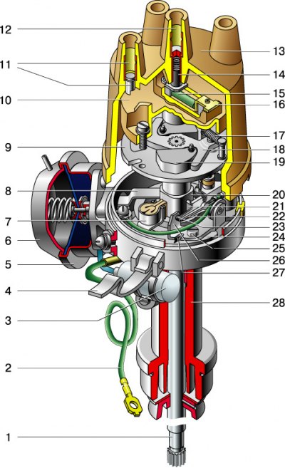
1 - roller; 2 - wire for supplying current to the distributor; 3 - capacitor; 4 - locking spring of the cover; 5 - housing of the vacuum regulator; 6 - membrane; 7 - felt; 8 – draft of the vacuum regulator; 9 – a basic plate of a regulator of an advancing of ignition; 10 – distributor rotor; 11 – side electrode with terminal; 12 – central electrode with terminal; 13 - distributor cover; 14 - coal of the central electrode; 15 - resistor; 16 - outer contact of the rotor; 17 - spring of the centrifugal ignition timing controller; 18 - leading plate of the centrifugal regulator; 19 - weight of the ignition timing regulator; 20 - breaker cam; 21 - insulating block of the lever; 22 - breaker lever with moving contact; 23 - breaker contacts; 24 - movable breaker plate; 25 - screw fastening the contact group; 26 - rack with a fixed contact of the breaker; 27 - groove; 28 - housing of the ignition distributor.
The ignition distributor converts the direct current of the low voltage circuit into pulsed current and distributes the high voltage current pulses to the spark plugs. It is structurally integrated with a breaker and ignition timing controllers.
The distributor is installed in front of the cylinder block on the left side.
The distributor body is cast from aluminum alloy. Two plain bearings are pressed into the housing shank, in which the roller rotates. A breaker cam is made on the upper part of the roller, and a centrifugal regulator and a rotor are mounted (slider). When the roller rotates, the weights of the centrifugal regulator diverge under the action of centrifugal forces and turn the tetrahedral cam of the interrupter at a certain angle in the direction of rotation of the roller. In this case, the contacts open with some advance, the greater, the higher the engine speed. The angle of rotation is limited by the size of the groove in the rotor base plate.
The interrupter consists of a rack with a fixed contact and a movable contact with a textolite stop, which is pressed by a flat spring against the four-sided cam of the distributor shaft. As the cam rotates, the contacts close and open. The cam is lubricated with a felt felt impregnated with engine oil.
Attention! When operating the car, it is necessary to systematically check and adjust the gap between the contacts of the breaker (see Adjustment of the angle of the closed state of the breaker contacts).
The plate on which the breaker mechanism is mounted is mounted on a ball bearing, allowing it to rotate around the axis of the roller. The plate is connected by a rod to the diaphragm of the vacuum ignition timing controller. Underpressure (brought through the hose from the throttle space of the carburetor) acts on the diaphragm of the vacuum regulator, and the rod turns the chopper mechanism together with the movable plate relative to the square cam, thus ensuring the optimum ignition timing depending on the engine load.
To reduce sparking between the contacts of the breaker, a capacitor is connected in parallel with them. It is fixed on the outside of the distributor housing.
From above, the distributor body is closed with a cover with sockets for high voltage wires. From the inside of the cover, a spring-loaded coal is mounted in its central electrode. Rotor with contact plate (slider) distributes the high voltage current to the spark plugs according to the firing order of the cylinders (1–3–4–2). The ignition distributor roller rotates clockwise (when viewed from above).
When adjusting the ignition timing, turning the distributor clockwise reduces the lead, counterclockwise increases it.