
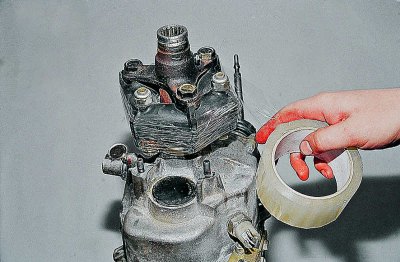
To facilitate the removal and subsequent installation of the elastic coupling, tightly wrap it with tape.
Opening with two keys «at 19» three nuts and removing three bolts, remove the clutch.
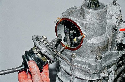
We remove the flange of the elastic coupling, the gearbox support, the speedometer drive (see Gearbox replacement).
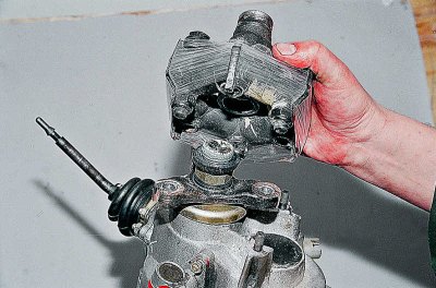
key «on 10» unscrew the three nuts securing the ball joint of the gear lever and...
... remove the lever from the studs of the rear cover of the gearbox.
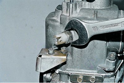
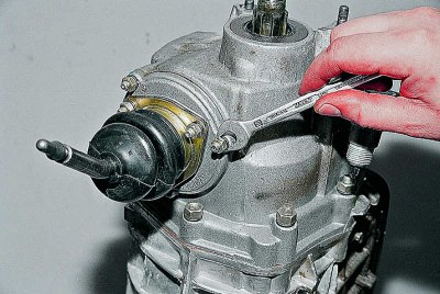
key «at 27» turn off the reverse light switch and...
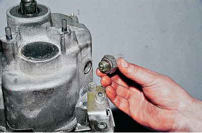
...remove it.
Remove the bottom cover of the gearbox (see Gearbox repair) And...
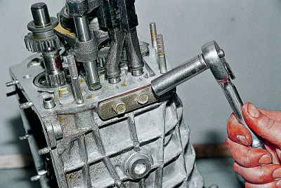
...the key «at 13» unscrew the nut securing the rear cover to the gearbox housing.
We unscrew the remaining nuts securing the rear cover to the gearbox housing (see Gearbox repair).
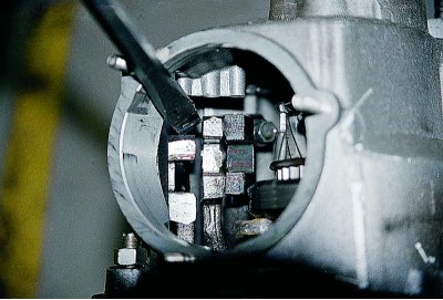
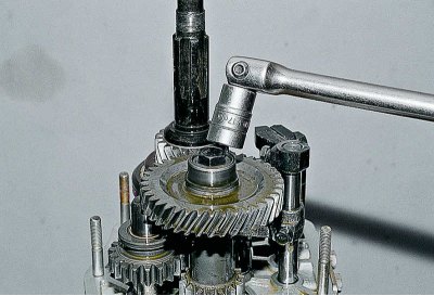
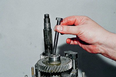
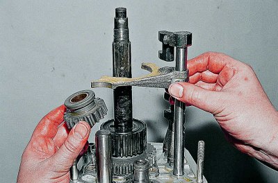
With a screwdriver, we drown the reverse gear and V gear.
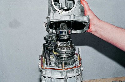
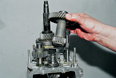
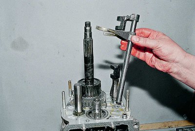
Remove the gearbox rear cover.
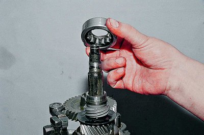
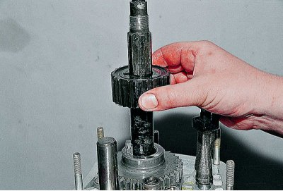
We remove the rear bearing of the secondary shaft and...
...its inner ring.
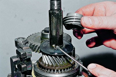
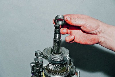
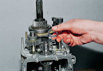
We remove the drive gear of the speedometer drive with a lock - a metal ball and...
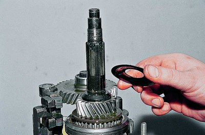
... an oil slinger.
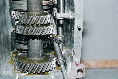
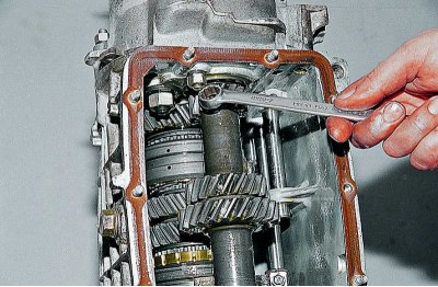
key «on 10» unscrew the bolt securing the fork of the inclusion of I and II gears.
Turn on the 2nd gear with a screwdriver.
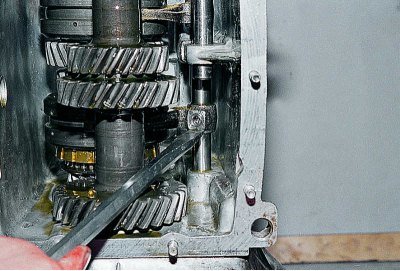
head «at 17» unscrew the bolt securing the gear unit.
Remove the gear block mounting bolt.
We take out the block of gears of the V transmission and reverse gear.
Remove the spacer.
key «at 13» I unscrew the two bolts securing the cover of the clamps and, having removed it,...
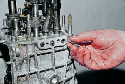
... we remove three springs and three balls of clamps.
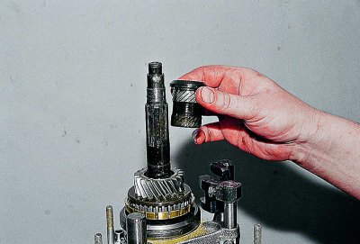
Remove the 5th gear bushing.
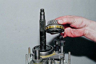
We remove the V gear assembly with the synchronizer.
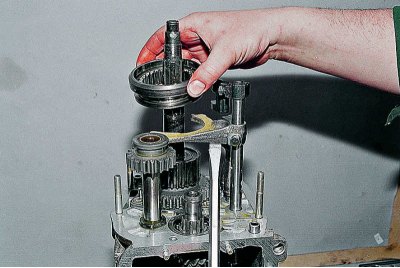
Raising the rod, remove the V gear synchronizer clutch and...
...reverse idler gear.
We remove the rod for engaging the V gear and reverse gear with a fork.
Remove the 5th gear synchronizer clutch hub.
Further disassembly of the gearbox is carried out in the order described above.
Assembly of the V stage, reverse gear and gear selection mechanism is carried out in the reverse order of disassembly, taking into account the following. Fasten the axis of the intermediate reverse gear before installing the shafts in the gearbox housing with a torque of 78 N.m (8 kgf·m). Before installing the 5th gear and reverse fork rod into the crankcase, put the spacer bushing on it. Press the inner ring of the bearing onto the gear block of the 5th gear and reverse gear, and the outer ring into the seat of the rear cover. Press the output shaft rear bearing onto the shaft to facilitate installation of the rear cover. Install the intermediate reverse gear, the driven gear of the 5th gear and its yoke at the same time. Tighten the gear block mounting bolt with a torque of 78 N.m (8 kgf·m).
Since 1992, five-speed gearboxes have not had a washer installed on the output shaft, and the configuration of the output shaft and the V gear synchronizer clutch hub has been changed. On the secondary shaft, the diameter for the hub was 28, it became 25 mm; the width of the landing part of the hub has become larger and the landing diameter has been reduced from 28 to 25 mm.
These parts are not interchangeable with previously produced ones, therefore, when repairing a gearbox «old» design, observe the following rules:
if the washer changes, then the output shaft and hub are put «old» constructions;
if parts of the same name are installed instead of the output shaft or hub «new» structures, then they must be changed as a complete set, that is, when the hub is replaced, the output shaft is also replaced and vice versa. In this case, the washer is not installed.
Permissible dimensions of gearbox wear parts
Mating Parts | Dimensions of mating parts | Permissible gap in mating, mm | |||||||
Hole | Shaft | ||||||||
Input shaft - front end of output shaft plus two bearing rollers | 25,328+0,021 |
2 (3-0,006) | Limit dimensions: | ||||||
Synchronizer Clutch Hub - Output Shaft |
| 38-0,030 | 0,05 | ||||||
Driven gears III and II gears - secondary shaft |
| 43,5-0,025 | 0,15 | ||||||
1st gear driven gear - driven gear bushing |
| 43,5-0,025 | 0,15 | ||||||
Sleeve of a conducted gear of the I transfer - a secondary shaft |
| 30,05-0,016 | 0,016 | ||||||
Reverse driven gear - output shaft | 29,95+0,030 | 29,95-0,021 | 0,051 | ||||||
Reverse Idler Gear with Bushing - Pinion Shaft |
|
| 0,15 | ||||||