




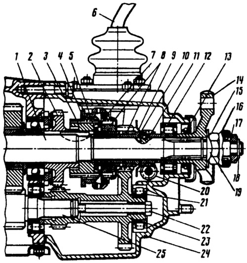
Fig. 122. Rear part of the five-speed gearbox:
1 - secondary shaft; 2 - reverse driven gear; 3 - hub of the synchronizer clutch U of the transmission; 4 - synchronizer clutch; 5 - washer; 6 - synchronizer locking ring; 7 - gear shift lever; 8 - gear and toothed ring of the synchronizer of the 5th gear; 9 - oil deflector washer; 10 - V gear bushing; 11 - speedometer drive pinion; 12 - secondary shaft rear bearing; 13 - oil seal; 14 - elastic coupling flange; 15 - nut: 16 - centering ring seal; 17 - centering ring; 18 - retaining ring; 19 - lock washer; 20 - driven gear of the speedometer drive: 21 - bearing of the gear block; 22 - gear block mounting bolt: 23 - 5th gear and reverse gear block; 24 - rear cover of the gearbox; 25 - intermediate shaft.
Changes have also been made to the gear shift drive. A gear selection mechanism has been introduced. It consists of a housing 3 (Fig. 123) of the gear shift lever, to which the guide plate 2 of the gear shift lever is attached with three bolts together with washers 1 and the reverse locking plate 12.
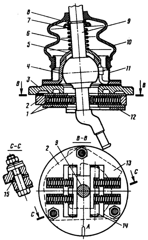
Fig. 123. Gear selection mechanism:
1 - guide plate washers; 2 - gear shift lever guide plate: 3 - gear shift lever housing; 4 - ball joint of the lever; 5 - spherical washer; 6 - spring; 7 - thrust ring; 8 - retaining ring; 9 - gear shift lever; 10 - protective cover; 11 - flange; 12 - reverse locking plate; 13 - spring; 14 - guide bar; 15 - sealing ring; A - risk.
In the grooves of the guide plate 2 there are spring-loaded guide strips 14, between which the lower part of the lever 9 is clamped.
The original is available on the website: vazbook