
Disassembly
Before removing the rear cover, place the gear lever in neutral position, unscrew the nuts securing the gear selector mechanism and remove the gear selector assembly with the mechanism. Then unscrew the nuts securing the rear cover and remove it. One of the cover fastening nuts is unscrewed from the inside of the gearbox housing with the bottom cover removed. When removing the rear cover, it must be fed not only back, but also rotated to prevent it from touching the reverse gear and fifth gear.
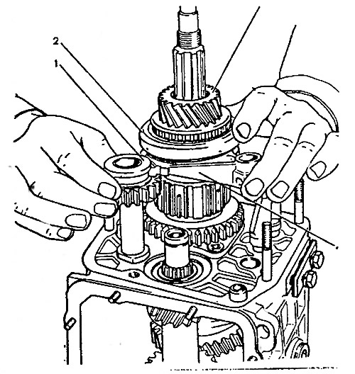
After removal from the secondary shaft of the inner ring of the rear bearing 12 (pic 3-31) and drive gear of the speedometer drive, loosen the cover fastening bolts 5 (pic. 3-32) clamps and unscrew bolts 2 and 4 fastening the gear unit and the fork for engaging the fifth gear and reverse gear. Remove oil deflector 9 (pic. 3-31), and then sleeve 1 (pic. 3-33) fifth gear and remove rod 1 (pic. 3-34) from the fork 2. At the same time, the distance sleeve 3 is removed from the rod. Then remove the gear unit 4 from the spline of the intermediate shaft.
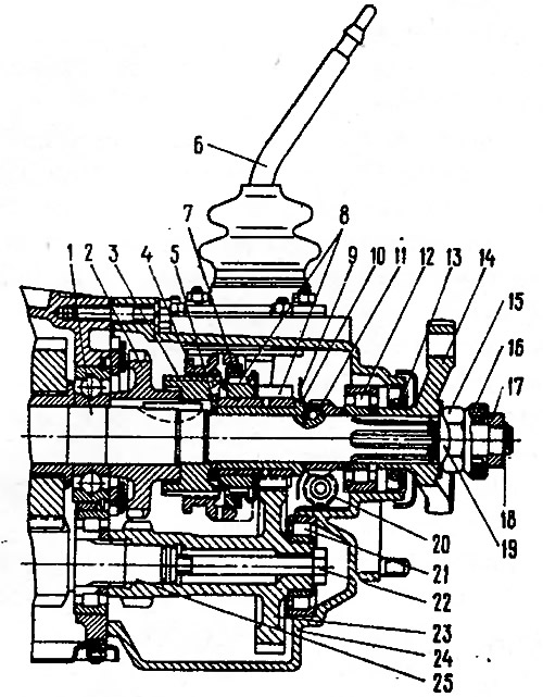
Pic. 3-31. Rear of the five-speed gearbox: 1 - secondary shaft; 2 - reverse driven gear; 3 - hub of the synchronizer clutch of the V transmission; 4 - synchronizer clutch; 5 - washer; 6 - gear lever; 7 - synchronizer blocking ring; 8 - gear and ring gear of the V gear synchronizer; 9 - oil slinger; 10 - bushing gear V gear; 11 - drive gear of the speedometer drive; 12 - rear bearing of the secondary shaft; 13 - stuffing box; 14 - flange of an elastic coupling; 15 - nut; 16 - centering ring seal; 17 - centering ring; 18 - retaining ring; 19 - lock washer; 20 - driven gear of the speedometer drive; 21 - gear block bearing; 22 - a bolt of fastening of the gear block; 23 - gear block of V gear and reverse gear; 24 - rear cover of the gearbox; 25 - intermediate shaft
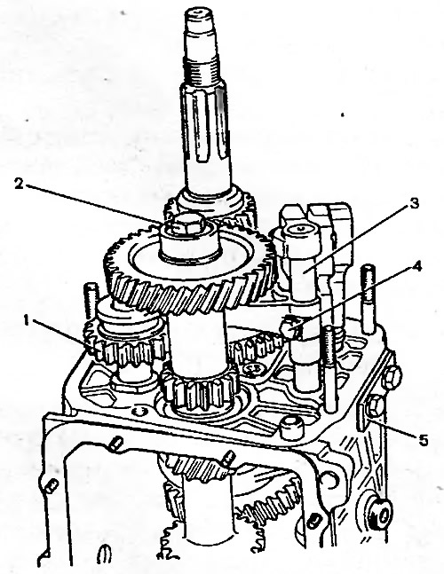
Pic. 3-32. Unscrewing the bolts of the gear unit and the fork for engaging the V gear and reverse gear: 1 - intermediate reverse gear; 2 - a bolt of fastening of the gear block; 3 - plug stem; 4 - fork fastening bolt, 5 - clamp cover
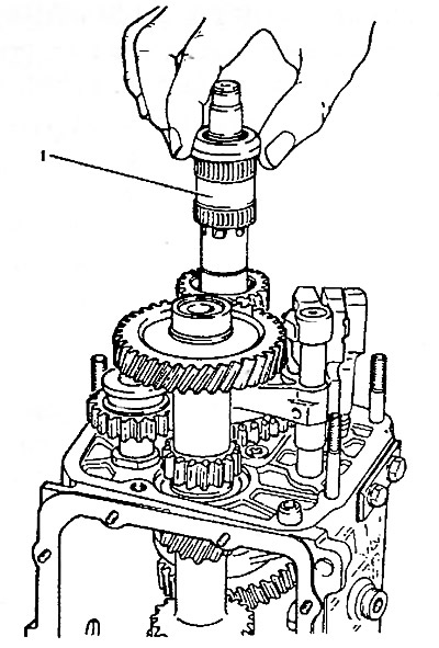
Pic. 3-33. Removing the 5th gear bushing: 1 - sleeve
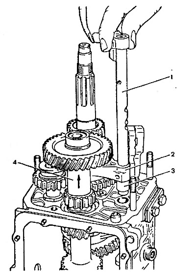
Pic. 3-34. Removing the fork rod for engaging the V gear and reverse and the gear block: 1 - fork rod for engaging V gear and reverse gear; 2 - fork for switching on V gear and reverse gear; 3 - remote bushing; 4 - gear block
Remove intermediate gear 1 at the same time (pic. 3-35) reverse gear from the axle, gear 3 complete with clutch and fork 4 from the secondary shaft.
Pic. 3-35. Removing the reverse gear, V gear assembly with synchronizer and fork: 1 - intermediate reverse gear; 2 - 5th gear engagement clutch; 3 - gear V transmission with synchronizer; 4 - fork for switching on V gear and reverse
Remove the washer 5 from the secondary shaft (pic. 3-31), and then with curly mandrels (screwdriver type) remove the hub 4 from the key (pic. 3-36) fifth gear synchronizer and reverse driven gear 2.
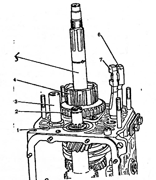
Pic. 3-36. Removing the reverse driven gear and the 5th gear synchronizer clutch hub: 1 - intermediate shaft; 2 - reverse driven gear; 3 - axis of the intermediate reverse gear; 4 - hub of the synchronizer clutch of the V transmission; 5 - secondary shaft; 6 - a rod of a fork of inclusion of I and II transfers; 7 - a rod of a fork of inclusion of III and IV transfers
Note. Puck 5 canceled since 1992 (see fig. 3-31) on the secondary shaft and the configuration of the secondary shaft 1 and hub 3 of the synchronizer clutch of the V transmission has been changed (on the secondary shaft, the diameter under the hub was 28 mm, it became 25 mm; the width of the seat part of the hub has become larger by the thickness of the washer and the seat diameter has been reduced from 28 mm to 25 mm) These parts are not interchangeable with previously produced ones, therefore, when repairing an old gearbox design, observe the following rules:
- if washer 5 changes, then the output shaft and hub are put «old» constructions;
- if instead of the secondary shaft or hub, the same-name parts of the new design are installed, then they must be changed as a set, that is, when the hub is replaced, the output shaft also changes and vice versa. In this case, the washer is not installed.
Carry out further disassembly of the gearbox in the order described for the four-speed gearbox.
If necessary, disassemble the lever and the gear selection mechanism, for which:
- remove protective cover 10 (pic. 3-37), retaining and thrust rings 8 and 7, spring and spherical washer 5 from the gear lever;
- visually mark the location of the parts relative to the mark A, printed on the guide plate, in order to connect the parts in the same position during assembly;
- having unscrewed the nuts from the fastening bolts, separate the parts of the gear selection mechanism and remove the lever 9, its ball joint 4 and rubber sealing rings 15.
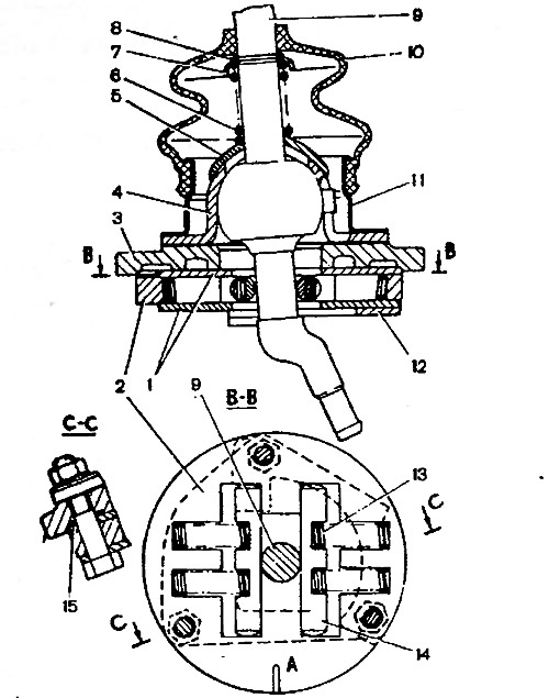
Pic. 3-37. Gear selection mechanism: 1 - washer of the guide plate; 2 - guide plate; 3 - gear lever housing; 4 - ball bearing; 5 - spherical washer; 6 - spring; 7, 8 - retaining rings; 9 - gear lever; 10 - protective cover; 11 - flange; 12 - reverse blocking plate; 13 - spring; 14 - guide bar; 15 - sealing ring; A - risk
Assembly
The assembly of the fifth gear, reverse gear and gear selection mechanism is carried out in the reverse order of disassembly, taking into account the following:
- fasten the axis of the intermediate reverse gear before installing the shafts in the gearbox housing with a torque of 78 Nm (8 kgf·m),
- before installing the fifth gear and reverse fork rod into the crankcase, install a distance sleeve on it;
- press the inner ring of the bearing onto the gear block of the fifth gear and reverse gear, and the outer ring into the socket of the rear cover;
- press the rear bearing of the secondary shaft onto the shaft to facilitate the installation of the rear cover;
- . intermediate gear 1 (pic. 3-35) reverse gear, gear 3 and fork 4 are installed at the same time;
- when assembling the gear lever, coat the ball head or ball bearing sphere with LSTs-15 or Litol-24 grease;
- tighten the gear block mounting bolt to a torque of 78 Nm (8 kgf·m).