




Attention! The gearbox consists of a large number of parts, many of which are similar, so to facilitate assembly, the parts should be laid out on sheets of paper in order and each one should be labeled.
Drain the oil from the gearbox (see Checking the level and replacing the oil in the gearbox).
Remove the gearbox (see Gearbox replacement).
Remove the clutch release fork and clutch release bearing (see Replacing the pressure plate assembly and clutch release bearing).
We thoroughly clean it from dirt, wash the gearbox housing with a brush and hot water with detergent on the outside and place it on the workbench with the clutch housing down.
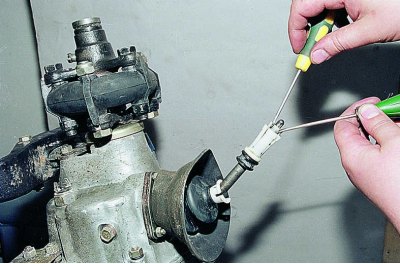
Using two screwdrivers, we spread the sectors of the spacer sleeve and...
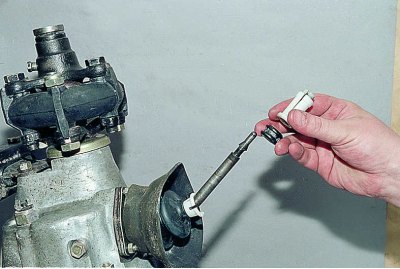
...we remove it and the rubber bushing of the damper.
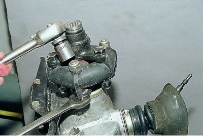
Remove the elastic coupling and flange from the secondary shaft of the gearbox (see Replacing the secondary shaft seal).
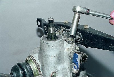
Using a 13 mm socket, unscrew the two nuts securing the support...
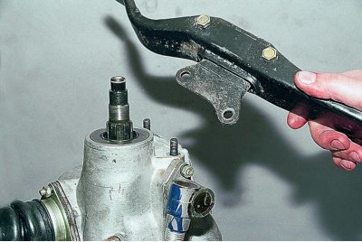
...and we take it off.
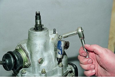
Using a 10 mm socket, unscrew the speedometer drive mounting nut...
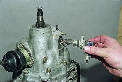
...and remove the speedometer drive.
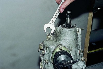
Using a 22 mm wrench, unscrew the reverse light switch...
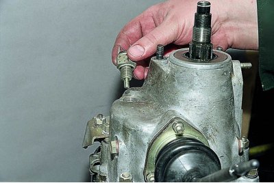
...and we take it off.
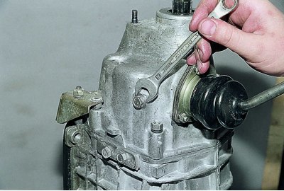
Using a 13 mm spanner, unscrew the gear shift lever stop.
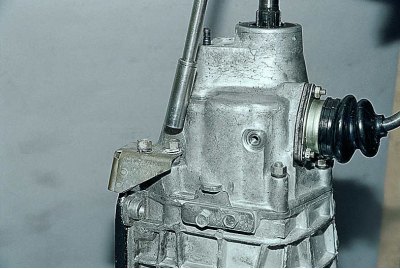
Using a 13 mm socket head, unscrew the two nuts securing the bracket.
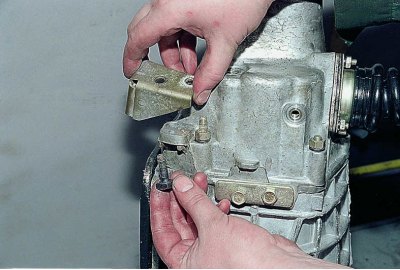
We remove the bracket and take out the square head bolt.
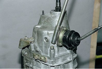
Using a 13 mm socket head, unscrew the remaining nuts securing the rear cover of the gearbox.
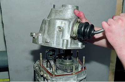
Remove the rear cover by moving the gear shift lever to the right to release it from the gear engagement rods.
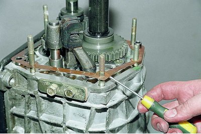
Carefully, trying not to damage it, remove the rear cover gasket.
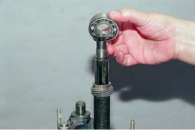
We remove the rear bearing.
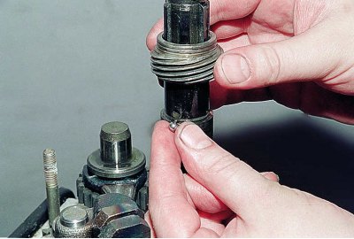
We remove the speedometer drive pinion and its retainer – a steel ball.
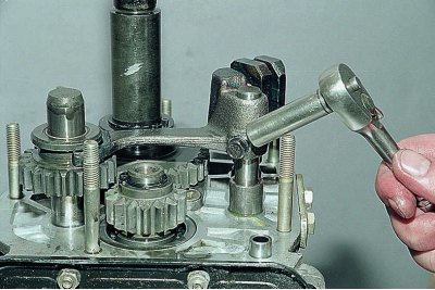
Using a 10 mm socket, unscrew the bolt securing the reverse gear fork.
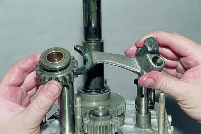
We remove the reverse gear engagement fork and the reverse gear intermediate gear.
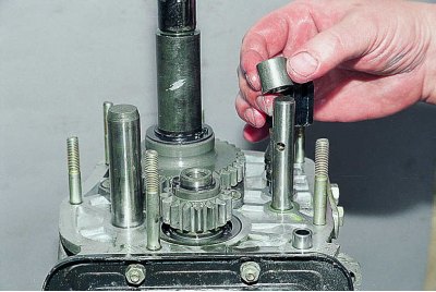
We remove the spacer sleeve from the reverse gear engagement rod.
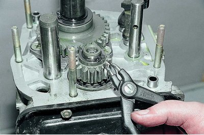
Using a puller, remove the retaining ring from the intermediate shaft.
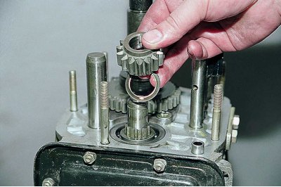
Remove the reverse drive gear and spring washer.
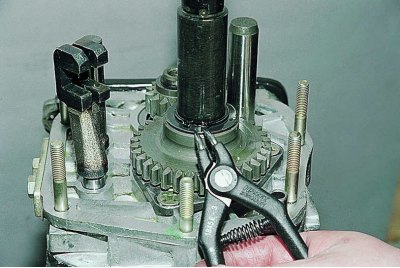
Using a puller, remove the retaining ring from the secondary shaft.
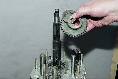
Remove the reverse driven gear and spring washer.
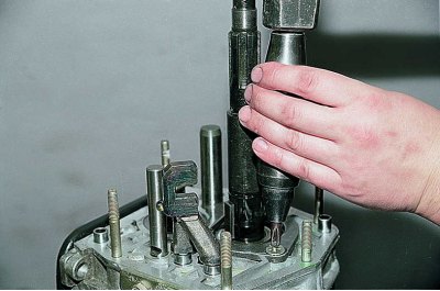
Using an impact screwdriver, unscrew the four screws securing the bearing lock plate and the reverse intermediate gear axle.
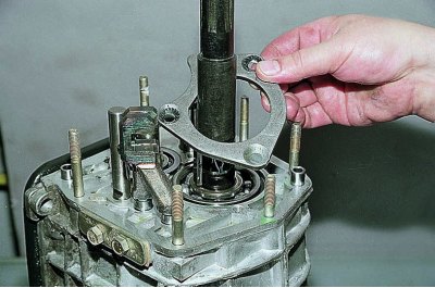
We remove the locking plate.
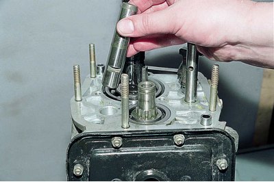
We take out the axle of the intermediate reverse gear.
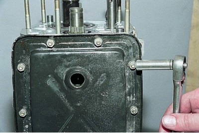
Using a 10 mm socket head, unscrew the ten nuts securing the bottom cover.
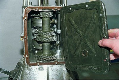
We remove the cover.
We put the gearbox on its side.
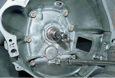
Using a 13 mm socket head, unscrew one nut...
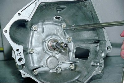
...and with a 17 mm head - six nuts securing the clutch housing to the gearbox.
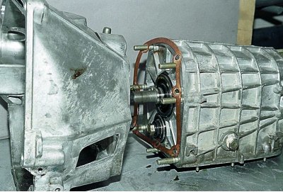
We separate the crankcases and remove the gasket.
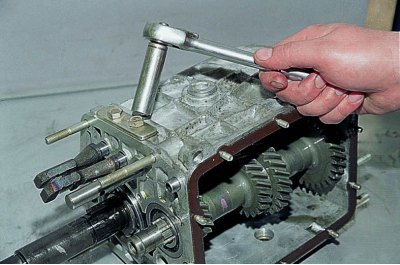
Using a 13 mm head, unscrew the two bolts securing the rod retainer cover.
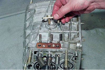
We remove the cover and remove three springs and three balls from the holes.
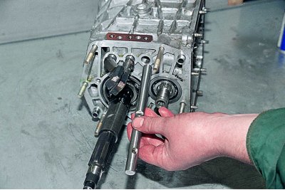
We take out the reverse gear engagement fork rod.
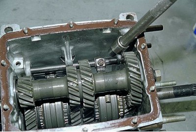
Using a 10 mm head, unscrew the bolt securing the fork for engaging 1st and 2nd gears.

We take out the rods, simultaneously removing the locking crackers.
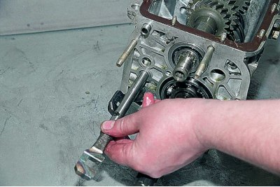
We take out the rod of the fork for engaging 1st and 2nd gears.
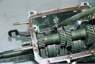
Using a 10 mm head, unscrew the bolt securing the fork for engaging III and IV gears.
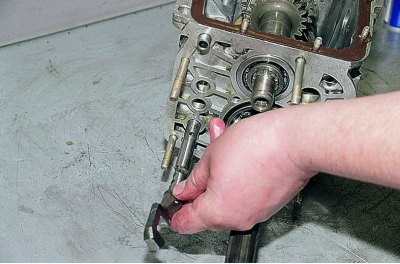
We take out the rod of the fork for engaging III and IV gears.
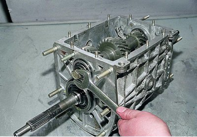
By pressing the clutches, we engage two gears at once and use a 19 mm wrench to unscrew the bolt securing the front bearing of the intermediate shaft.
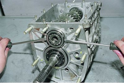
Using two screwdrivers, pry up the retaining ring and remove the front bearing of the intermediate shaft.
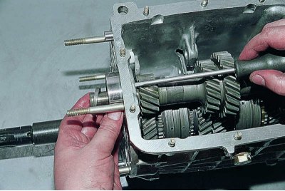
We push out the rear bearing of the intermediate shaft.
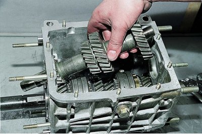
By tilting it, we remove the intermediate shaft from the gearbox housing.
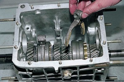
We take out two gear shift forks.
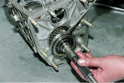
Using a screwdriver, we remove the primary shaft assembly with the bearing and synchronizer ring.
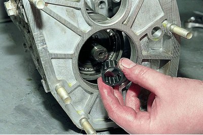
We remove the needle bearing from the secondary shaft.
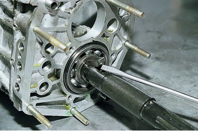
Using a screwdriver, we remove the key from the rear of the secondary shaft.
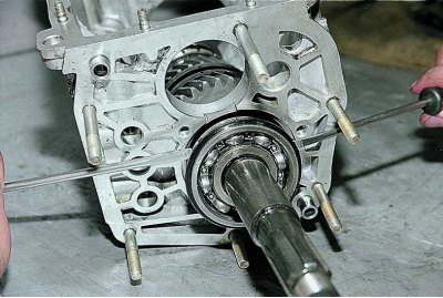
Using two screwdrivers, remove the rear bearing of the secondary shaft.
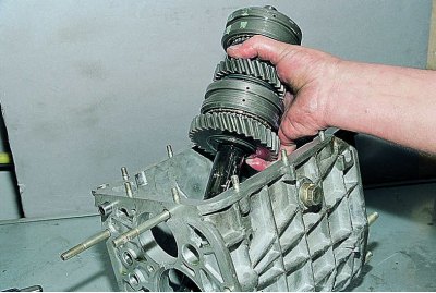
We remove the secondary shaft from the gearbox housing.
We install the secondary shaft vertically, clamping it in a vice through cardboard spacers.
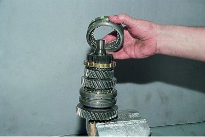
We remove the synchronizer clutch of III and IV gears.
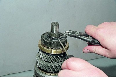
We remove the retaining ring using a puller...
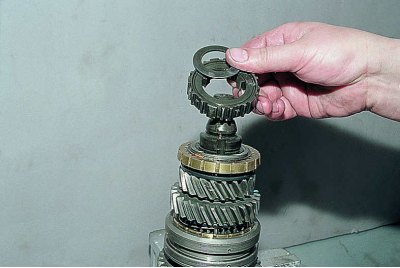
...and remove the synchronizer hub and spring washer.
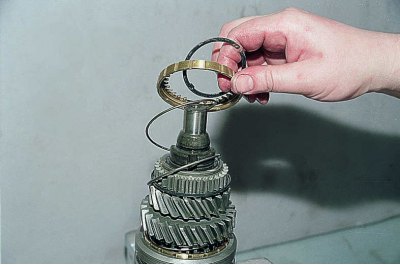
Using a screwdriver, remove the retaining ring, as well as the locking ring and the synchronizer spring.
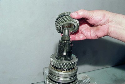
We remove the third gear.
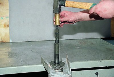
Having supported the 1st gear pinion on a rigid base, we knock out the secondary shaft with a hammer through a soft metal spacer...
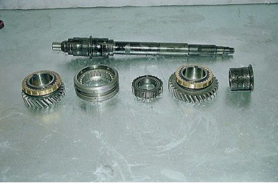
...and remove from it the 2nd gear assembly, the synchronizer clutch of the 1st and 2nd gears, the synchronizer hub, the 1st gear assembly and the 1st gear sleeve.
Synchronizer elements I, II and IV (on the primary shaft) the gears are disassembled in the same way as the synchronizer of the third gear.
To remove the primary shaft bearing...
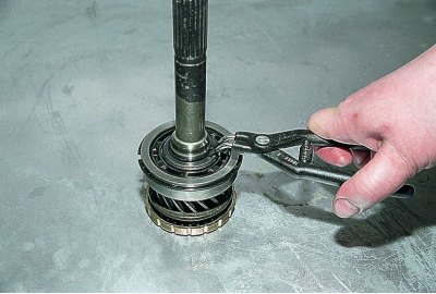
...we use a puller to loosen the retaining ring...
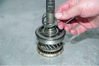
...and remove it together with the spring washer.
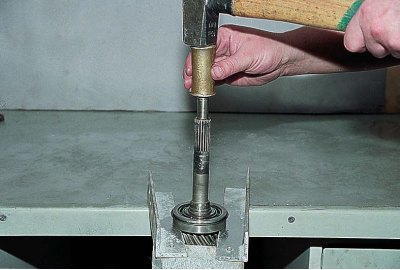
Having supported the bearing on a rigid base, we knock out the primary shaft with a hammer through a soft metal punch.
To remove the gear shift lever from the rear cover of the gearbox housing...
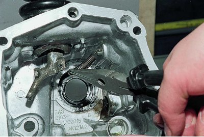
...we disconnect the return spring from the lever.
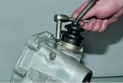
Using a 10 mm spanner, unscrew the three nuts securing the ball joint of the lever and...
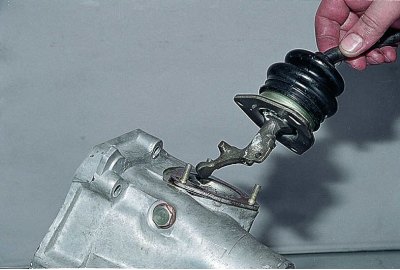
...we remove the lever from the studs.
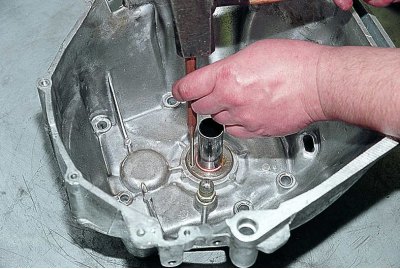
To replace the master cuff (primary) we knock out the shaft seal with a punch through the hole in the front cover of the gearbox and...
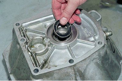
...we take it off.
We thoroughly wash all the parts in kerosene or diesel fuel and inspect them. There should be no chips, burrs, fatigue pitting or noticeable wear on the teeth of the gears and couplings. The surfaces of the shafts, axles and gearshift rods should be completely smooth, without burrs, cavities or severe wear. There should be no cracks or nicks on the crankcase, and no wear or signs of turning in the bearing bores. There should be no corrosion or signs of crushing or jamming on the shaft splines. Minor damage can be repaired with fine sandpaper followed by polishing, but it is better to replace damaged parts with new ones.
All rolling bearings, both ball and roller, must be in perfect condition, their radial clearance must not exceed 0.05 mm, any defects on the raceways and rolling elements are unacceptable. Separators must not have breaks, ring touches or melting (in plastic). In general, if the gearbox "mileage" exceeds 120 thousand km and the unit is being repaired with disassembly, it is better to replace all bearings with new ones regardless of their condition, especially if severe damage to the gears and gear engagement clutches was noticed. The cuffs are replaced with new ones in any case. During assembly, lubricate all parts of the gearbox, including bearing seats and the bearings themselves with transmission oil, cover the joints of the crankcase and covers with a thin layer of oil-resistant sealant, and the parts of the gearshift mechanism with SHRUS-4 grease.
We assemble the gearbox in the reverse order of disassembly. The spring of the reverse fork rod retainer differs from others in rigidity and has a black coating. Before installation, cover the working surface of the cuffs with a thin layer of Litol-24 grease. Tighten the intermediate shaft bearing clamp washer bolt with a torque of 8.1–10.0 kgf·m. Tighten the secondary shaft rear end nut with a torque of 6.8–8.4 kgf·m.