Primary shaft 1 (figure 77) is made in the form of a gear block rotating in two bearings. The driving gears of the primary shaft are in constant engagement with the driven forward gears located on the secondary shaft 20 on needle bearings 19. In addition to them, two synchronizers 16 and 18 are installed on the secondary shaft. The driving gear of the main transmission is made together with the secondary shaft. The differential is two-satellite. The preliminary tension in the differential bearings is adjusted by selecting the thickness of ring 14. The driven gear 13 of the main transmission is fastened to the flange of the differential box with bolts.
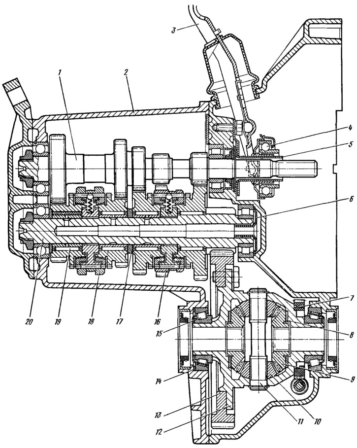
Figure 77. Gearbox: 1 — primary shaft; 2 - gearbox housing; 3 - clutch release fork; 4 — clutch release bearing; 5 — release bearing clutch guide sleeve; 6 - oil sump; 7 — speedometer drive pinion; 8 - axle gear support washer; 9 — axle shaft gear; 10 - satellite; 11 — satellite axis; 12 — differential box, 13 — driven gear of the main transmission; 14 adjustment ring; 15 — differential bearing; 16 — synchronizer of 1st and 2nd gears; 17 — thrust ring; 18 — synchronizer of III and IV gears; 19 — secondary shaft gear needle bearing; 20 — secondary shaft
The gearbox control drive consists of a lever 16 (figure 78) gear shift, ball joint 19, rod 15, hinge 10, 11, 12, rod 6 for selecting gears and gear selection and shifting mechanisms. In order to prevent spontaneous gear disengagement due to axial movement of the power unit on its supports when the vehicle is moving, a reaction rod 18 is introduced into the gearbox control drive, one end of which is rigidly connected to the power unit, and the other rests on sleeve 17 of the lever support, the collar of which is attached to the body floor. In this sleeve, the reaction rod moves freely. The ball joint of the gear shift lever is attached not to the body floor, but to the reaction rod, therefore, the axial movement of the power unit is not transmitted to the lever and the gear selection mechanism.
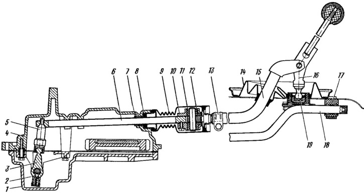
Figure 78. Gear shift drive: 1 - gearbox housing; 2 - retainer; 3— gear selection lever; 4 — clutch housing; 5 — gear selection rod lever; 6 - gear selection rod; 7 — rod bushing; 8 — rod seal; 9— protective cover; 10 — hinge housing; 11 — hinge bushing; 12 — hinge tip; 13 — clamp; 14 — protective cover of the traction; 15 — gear shift drive rod; 16 — gear shift lever; 17 — thrust bushing; 18 - jet thrust; 19 — ball joint of the gear shift lever.
The original is on the portal (VazBook.ru)
On the inner end of the gear selection rod 6, a lever 5 is fixed, into the socket of which the head of the two-arm lever 3 of the gear selection mechanism enters. This mechanism is made as a separate unit and is fixed to the plane of the clutch housing 4.
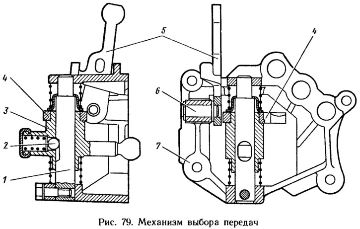
In building 7 (figure 79) the gear selection mechanism is secured with a locking bolt by the axle 1, on which the double-arm gear selection lever 4 is mounted. A ball lock 2 is located in its hub, and the axle has a recess for the locking ball. The gear selection lever 3 is expanded on both sides by springs, under the action of which it is set to the position of engaging the third and fourth gears. The axle 6 is installed in the housing of the gear selection mechanism together with the fork 5 for engaging the reverse gear. The axle of the fork is fixed with a locking ring, and the leash of the head of the reverse gear rod enters the fork socket.