
The five-speed gearbox is designed on the basis of the previously installed on cars of the family «Satellite» four-speed box (fig.1).
The main difference between the five-speed gearbox is the additionally introduced fifth gear, the gears of which are installed in an enlarged rear cover. Otherwise, the designs of the boxes are identical, therefore, the features of the general device are considered using the example of a four-stage box; the features of the five-stage are shown separately in Fig.2.
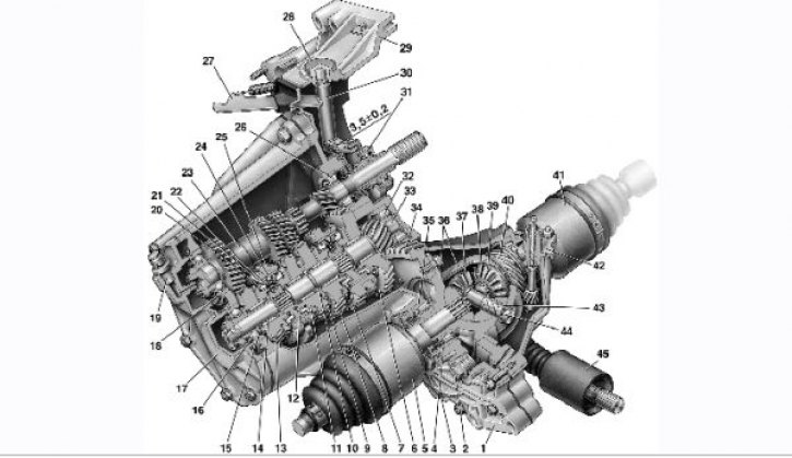
Gearbox four-speed: 1 - box crankcase; 2 - plug of the filling and control holes; 3 - drain plug; 4 - adjusting ring; 5 – left front wheel drive; 6 - driven gear of the 1st gear of the secondary shaft; 7 - synchronizer clutch of I, II gears with reverse gear; 8 - driven gear of the second gear of the secondary shaft; 9 - retaining ring; 10 - persistent half ring; 11 - driven gear of the third gear of the secondary shaft; 12 – a hub of the coupling of the synchronizer of III and IV transfers; 13 - driven gear of the fourth gear of the secondary shaft; 14 - needle bearing gears of the secondary shaft; 15 - thrust washer of the fourth gear gear; 16 - ball bearing of the secondary shaft; 17 – a back cover of a transmission; 18 - ball bearing input shaft; 19 - breather; 20 – a blocking ring of the synchronizer; 21 - sliding clutch of the synchronizer of III and IV gears; 22 - retainer cracker; 23 - input shaft; 24 - lock ball; 25 - fork of the sliding clutch of the synchronizer of III and IV gears; 26 - roller bearing input shaft; 27 - clutch release fork lever; 28 - clutch release fork bushing; 29 - clutch housing; 30 - clutch release fork; 31 - clutch release bearing; 32 - roller bearing of the secondary shaft; 33 - secondary shaft; 34 - driven gear of the main gear; 35 - roller tapered differential bearing; 36 - differential box; 37 - satellite; 38 – lock ring side gear; 39 - side gear; 40 - drive gear of the speedometer drive; 41 – right front wheel drive; 42 - speedometer drive; 43 - the axis of the satellites; 44 - retaining ring of the axis of the satellite; 45 – a protective cover of the hinge of a drive of a gear change
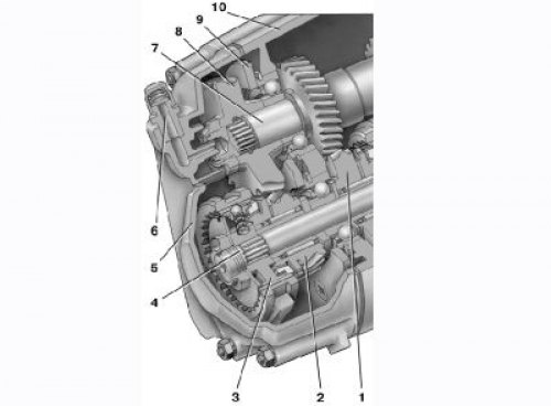
Rear of the five-speed gearbox: 1 - driven gear of the fourth gear of the secondary shaft; 2 - driven gear of the V transmission of the secondary shaft; 3 - synchronizer of V transmission; 4 - secondary shaft; 5 – a back cover of a case of a transmission; 6 - breather; 7 - input shaft; 8 - drive gear V transmission; 9 - thrust plate for mounting bearings; 10 - gearbox housing
Note. For later production boxes, the oil filler and control plugs were removed and replaced with a dipstick mounted at the top of the crankcase.
Input shaft 23 (see fig.1) made in the form of a block of driving gears, which are in constant engagement with the driven gears of all forward gears. They are located on needle bearings on the output shaft 33.
In addition to them, two synchronizers are installed on the shaft. Together with the secondary shaft, the final drive gear was made. Double satellite differential. The preload in the differential bearings is adjusted by selecting the thickness of the ring 4.
The driven gear 34 of the main gear is attached to the flange of the differential box. The five-speed gearbox has lengthened primary and secondary shafts at the outlet of the crankcase.
On this part of the shafts are the leading 8 (see fig. 2) and driven 2 gears of the V gear and its synchronizer 3. This gearbox has a sleeve 12 in the gear selection mechanism (see fig.3) not installed.
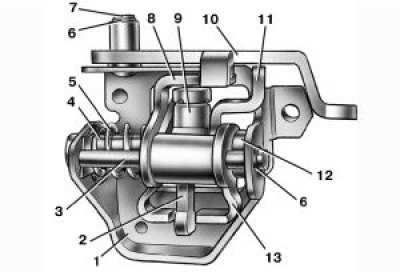
Gear selection mechanism: 1 - housing of the gear selection mechanism; 2 - gear selection lever (forward); 3 - guide axis of the locking brackets; 4 – an axis of the lever of a choice of transfers; 5 - spring; 6 - retaining ring; 7 - axis of the reverse fork; 8, 13 - blocking brackets; 9 – a clamp of the lever of a choice of transfers; 10 – a fork of inclusion of a backing; 11 - gear selection lever (reversing); 12 - thrust sleeve
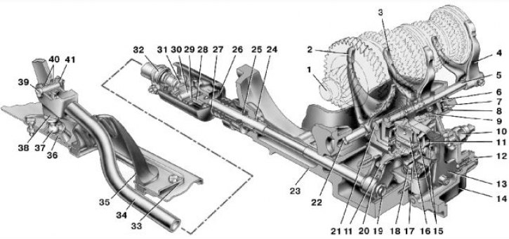
Gearbox control drive: 1 - secondary shaft; 2 – a fork of switching of I and II transfers; 3 – a fork of switching of III and IV transfers; 4 – fork of inclusion of V transfer; 5 – a rod of a fork of inclusion of V transfer; 6 - lock ball; 7 – retainer spring; 8 - latch cover; 9 - guide axis of the locking brackets; 10 – the switch of a lantern of a backing; 11 - three-arm gear selection lever; 12 – stopper of a clamp of a plug of inclusion of a backing; 13 – a fork of inclusion of a backing; 14 - gearbox housing; 15 - locking brackets; 16 - housing of the gear selection mechanism; 17 – an axis of the lever of a choice of transfers; 18 – a spring of the lever of a choice of transfers; 19 – a stock of a choice of transfers; 20 – gear selection rod lever; 21 – a rod of a plug of switching of III and IV transfers; 22 – a rod of a fork of switching of I and II transfers; 23 - clutch housing; 24 - bushing; 25 - stem gland; 26 - conical screw fastening the hinge; 27 - protective cover of the hinge; 28 – the case of the hinge of draft of a drive of a gear change; 29 - hinge bushing; 30 - hinge axis; 31 - hinge tip; 32 – a collar of draft of a drive of a gear change; 33 – the case of the lever of a gear change; 34 - thrust of the gear shift drive; 35 – a protective cover of draft; 36 - ball bearing of the lever; 37 - spherical finger of the lever; 38 - gearshift lever; 39 - the axis of the lever; 40 - bushing of the lever axis; 41 - locking bracket.
The gearbox control drive consists of a lever 38 (fig.4) gear shift, ball joint 36, rod 34, gear selection rod 19 and mechanisms for selecting and shifting gears. At the inner end of the rod 19, a lever 20 is fixed, which acts on the three-arm lever 11 of the gear selection mechanism.
This mechanism is made as a separate unit and is attached to the plane of the clutch housing 23. In building 1 (fig.3) gear selection mechanism fixed two axles. Axle 4 has a three-arm gear selection lever, two locking brackets 8 and 13, and a bushing 12.
The other axis 3 passes through the hole in the hub of the locking brackets, fixing them from turning. Lever arm 2 for gear selection is used to engage forward gears, arm 11 is used to engage reverse gear, and lever 20 acts on the third arm (see fig.4) rod 19 gear selection.
A latch 9 is mounted in the hub of the gear selector lever (see fig. 3). A fork 10 for reversing is installed on the axis 7. Gearboxes are produced with different final drive ratios.
To distinguish the secondary shaft, grooves are machined on its ring gear: two on the left (the crown of the shaft is located to the right of the observer) for a 17 tooth ring, one on the left for a 16 tooth ring, one on the right for a 15 tooth ring.
On the driven gears of the main gear, the gear ratio is marked (For example, «65/15»).
To distinguish gearboxes by gear ratios of the main gear, they are marked with paint. The marking is applied on the top of the gearbox housing: «01» for gear ratio 3.9; «02» for gear ratio 4.1; «03» for gear ratio 3.7; «00» for a gear ratio of 4.1 five-speed gearbox.
Helpful Hints: The manufacturer does not give unambiguous recommendations on the oils used for the gearbox. Either engine oil or various gear oils are recommended. Therefore, decide which oil to use, depending on the operating conditions of the car.
If the car is operated mainly in a large city with frequent gear changes, use engine oil, since in this case a relatively large synchronizer resource is provided.
If you have to drive mainly on highways at high speeds, but with relatively rare gear changes, it is better to use gear oil that provides an increase in the life of gears and bearings while slightly reducing the durability of synchronizers.
Try to fill the box with a little more oil when refueling (about 100 ml), than recommended by the manufacturer. This will provide better operating conditions for the 5th gear bearing located high in the crankcase and splash lubricated only.