
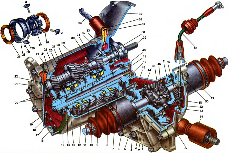
1. Transmission housing. 2. Tapered roller differential bearing. 3. Adjusting ring. 4. Drain plug. 5. Axle seal (wheel drive joint housings). 6. Left front wheel drive. 7. Gear wheel of the 1st gear of the secondary shaft. 8. Clutch synchronizer I, III gears and reverse. 9. Gear wheel of the second gear of the secondary shaft. 10. Thrust ring. 11. Gear wheel of the third gear of the secondary shaft. 12. Synchronizer hub III and IV gears. 13. The gear wheel of the IV gear of the secondary shaft. 14. Thrust washer of the fourth gear gear. 15. Ball bearing output shaft. 16. The rod of the fork of inclusion of I and II gears. 17. Rod of the fork of inclusion of III and IV gears. 18. Secondary shaft. 19. Reverse fork rod. 20. Bearing adjusting ring. 21. The rear cover of the gearbox. 22. Ball bearing input shaft. 23. Oil gauge. 24. Drive gear of the IV gear of the input shaft. 25. Gear needle bearing. 26. Blocking ring of the synchronizer of III and IV transfers. 27. Fork of the sliding clutch of the synchronizer of III and IV gears. 28. Sliding clutch of the synchronizer of III and IV gears. 29. Retainer cracker. 30. Retainer ball. 31. Plate. 32. Roller bearing input shaft. 33. Primary shaft seal. 34. Clutch release fork. 35. Clutch housing. 36. Breather cap. 37. Breather. 38. Clutch release bearing. 39. The primary shaft of the gearbox. 40. Roller bearing of the secondary shaft. 41. Oil sump. 42. Driven gear of the main gear. 43. Differential box. 44. Support washer of the gear wheel of the axle shaft. 45. A lock ring of a cogwheel of a semiaxis. 46. Axle gear wheel. 47. Speedometer drive gear. 48. Speedometer drive cable assembly. 49. Right front wheel drive. 50. Speedometer drive housing. 51. Satellite. 52. Retaining ring of the axis of the satellites. 53. The axis of the satellites. 54. Protective cover of the gearshift drive hinge. 55. Gear selection rod.
To change the magnitude and direction of the torque transmitted from the engine to the driving wheels of the car, a two-shaft, four-speed gearbox with helical gears is used. The gearbox is combined with the main gear and differential and is characterized by the following gear ratios: first gear - 3.7; second gear - 2.06; third gear - 1.27, fourth gear - 0.9; reverse gear - 3.67; main gear - 4.54. All forward gears are synchronized.
Selected gear ratios provide good vehicle dynamics, high average speed and economical engine operation. Constant mesh helical gears and synchronizers in all forward gears ensure quiet operation of the gearbox, reliability and durability of its operation.
The gearbox is attached to the clutch housing 35 on studs, while a cargo bolt is installed under one of the fastening nuts to support the power unit when it is removed or installed. The second cargo bolt is mounted on the engine cylinder head.
In the crankcase 1 of the gearbox are the input shaft 39, the secondary shaft 18 with driven gears and two synchronizers, the axis of the intermediate reverse gear, main gear, differential and gear shift drive. The crankcase is closed with a back cover 21.
Carter
Carter 1 is cast from aluminum alloy. It has sockets for bearings 22, 15 and 2 of the primary and secondary shafts and differential, three sockets for gearshift rods 16, 17, 19, perpendicular to which the sockets of the rod clamps are located. Balls 11 are installed in these sockets (see ch. 20) with springs 13, which are closed with screw plugs. The opposite ends of the rods go into the sockets of the housing 21 of the gear selection mechanism, which is attached to the clutch housing with four bolts. Between these nests are crackers 3 of the locking device.
There is a drain hole at the bottom of the gearbox housing to drain the used oil. The drain hole is closed with a screw plug 4 (see ch. 19).
So that during the rotation of the gears and the spraying of oil in the crankcase, pressure is not created, the cavity of the gearbox housing communicates with the atmosphere through the breather 37. The breather tube is pressed into the hole of the clutch housing. A rubber cap 36 is put on top of the tube. To prevent oil ejection through the breather, the breather cavity is isolated from the gearbox cavity by plate 31, which is attached to the clutch housing with screws.
Back cover
The ball bearings of the primary and secondary shafts are closed by the back cover 21, in which there is a channel for the mass gauge ruler 23. The ruler has marks indicating the maximum and minimum oil levels in the gearbox. The ruler is sealed in the opening of the lid with a rubber stopper.
Outside, in the upper part of the cover, there is a tide in which a socket is made for the rubber bushings of the clutch cable damper.
Input shaft
The input shaft 39 of the gearbox is made in the form of a block of drive gears rotating in two bearings. The roller bearing 32 is pressed into the clutch housing 35, the ball bearing 22 is pressed into the gearbox housing. It fixes the input shaft from axial displacement and is attached to the shaft with a nut, and in the crankcase seat with an adjusting ring 20. The nut is caulked after tightening. The bearing adjusting ring is pressed against the crankcase wall by the rear cover.
At the outlet of the clutch housing, the input shaft is sealed with a seal 33, the working edge of which is pressed against the polished shaft belt. The shaft passes through the guide sleeve of the clutch release 38, which, with its flange, is fastened with three bolts to the clutch housing. The gear block includes driving gears of I, II, III, IV gears and reverse. The reverse gear, unlike other gears, is spur.
Output shaft
The output shaft 18 is made together with the drive gear of the eye gear. On the surface of the shaft, four belts were machined to accommodate gears, and slots were cut in two places for fastening the synchronizer hubs. To reduce friction losses and increase the efficiency of the gearbox, the gears on the output shaft are mounted on needle bearings 25 of the same dimension with a one-piece plastic cage. The secondary shaft is stepped, which made it possible to maintain optimal gaps between the teeth of the gears. In order to ensure the assembly of synchronizers and gears on the shaft with this shape of the shaft, the size of the needle bearings is selected according to the girdle of the shaft of the largest diameter. Therefore, the rest of the bearings are located on bushings of the same size as the shaft collar for the gear wheel 7 of the first gear.
A thrust ring 10 is installed between the needle bearings and the gears of the 2nd and 3rd gears, and a thrust washer is installed between the drive gear of the main gear and the gear of the 1st gear.
To improve the lubrication of needle bearings, an axial channel and radial holes are drilled in the secondary shaft, and internal annular grooves are machined in the bearing bushings, coinciding with the radial holes of the shaft, as well as holes along the radius in the bearing area. From the end of the secondary shaft, the shank of the oil collector 41 is installed in the axial channel.
When the shaft rotates, the oil is sprayed by the gear wheels and through the guide channel in the clutch housing enters the oil chamber behind the front bearing 40 of the secondary shaft and then through the oil sump 41 into the axial channel of the shaft and is ejected through the radial holes to the gear wheel bearings due to centrifugal forces.
The output shaft rotates in a roller bearing 40 and a ball bearing 15. The latter is pressed into the gearbox housing, and a thrust washer 14 is installed between it and the fourth gear gear bearing bush. The ball bearing 15 is fixed in the crankcase seat and on the shaft in the same way as the input shaft ball bearing 22, adjusting ring 20. The roller bearing 40 is pressed into the clutch housing together with the oil sump.
The gear wheels of the secondary shaft are arranged in the same way and differ from each other in size. Each wheel has two crowns: helical for engagement with the drive gear of the input shaft and a spur ring of the synchronizer. Before the crown of the synchronizer on the gear wheel there is a conical belt, on which the blocking ring 26 of the synchronizer is located.
Synchronizer
The synchronizer ensures shockless gear shifting. It consists of a hub 12, a clutch 28, crackers 29. springs and two blocking rings 26. The synchronizer hub is mounted on the pins of the output shaft and clamped: at the synchronizer of III and IV gears between the needle bearing bushes, at the synchronizer of I and II gears - between the needle bushing bearing and output shaft shoulder.
The hub has six grooves, three of which are drilled sockets for the retainer springs. In these grooves there are crackers 29 with retainer balls. Slots are cut along the outer diameter of the hub 12, along which the sliding sleeve 28 of the synchronizer can move. It has sockets inside for balls of retainers, and outside - an annular groove for the shift fork 27.
On both sides of the clutch there are bronze blocking rings 26, each having six protrusions that go into the grooves of the hub. In this case, three short protrusions go into the grooves in which the clamps are located, and longer and wider ones go into other grooves. These protrusions are installed in grooves with a side clearance equal to half the thickness of the coupling tooth (hubs). When this gap is selected, the angle of rotation of the blocking ring relative to the hub is limited. With this connection, the hub rotates together with the blocking rings. The conical part of the blocking rings are located on the conical belts of the gear wheels of the secondary shaft. When the gear is engaged, these conical surfaces are in contact. To increase the friction forces, threads are cut on the contact surfaces of the rings and longitudinal grooves are made. As a result, the oil film breaks at the point of contact and the frictional properties of the conical surfaces increase. The blocking ring has a gear ring, the teeth of which are beveled at a certain angle. A sliding clutch is connected to the ring gear of the blocking ring when the gear is engaged.
Sliding clutch 28 has an internal crown, which it is located on the teeth of the hub. The ends of the coupling teeth are beveled at the same angle as the teeth of the blocking rings and synchronizer rims. To prevent self-disengagement of gears under load, the teeth of the gear synchronizer crown are made conical, and the teeth of the sliding clutch have undercuts.
Reverse intermediate gear
Intermediate gear wheel 8 reverse (see ch. 20) located on the tubular axle 4, the ends of which rest in the holes of the clutch housing and gearbox. The gear wheel rotates on an axle on a bronze bushing. The ring gear of the wheel is spur-toothed, beveled at a slight angle from the end for better engagement of the gear wheels when reverse gear is engaged. On the gear wheel there is an annular groove for the reverse fork 7. To prevent self-disengagement of the reverse gear under load, the teeth on all reverse gears are made with a reverse taper in the direction of the tooth. When the reverse gear is turned on, the intermediate gear wheel 8 connects the gear wheel 54 of the input shaft with the ring gear of the clutch 53 of the synchronizer of I and II gears. At the same time, the reverse gear fork presses on the indicator lamp switch rod, and the lamp circuit is closed.
The main gear consists of a pair of helical spur gears. The driving gear is made together with the secondary shaft, driven 42 (see pic) made in the form of a crown, which is bolted to the flange of the differential box 43.
The differential is conical with two satellites 51 mounted on the axle 53, which is held in the differential box by retaining rings 52. Grooves are cut on the landing belts of the axle to improve the lubrication conditions for the contact surfaces of the satellites and the axle.
The gears of the semi-axes 46 rest on the ends of the bronze washers 44, the selection of the thickness of which regulates the axial movement of each gear; it should be no more than 0.1 mm. Each gear wheel of the axle shaft is mounted on the pins of the wheel drive hinge housing 49 and is held on it by a retaining ring 45. At the outlet of the clutch housings and the gearbox of the internal hinge housing (axle shafts) sealed with gaskets 5.
The differential box rotates in two tapered roller bearings 2, the preload in which is regulated by selecting the thickness of the adjusting ring 3. A plastic drive gear 47 of the speedometer drive is pressed onto the differential box.
The driven gear wheel of the speedometer drive with its roller rests on two ceramic-metal bushings: one is pressed into the clutch housing, the second is pressed into the speedometer drive housing.
At the outlet of the housing, the shaft of the gear wheel is sealed with a cuff. The speedometer drive 50 assembly is attached to the clutch housing with a nut and a stud, sealed in it with a rubber ring and sealed. A union nut for fastening the cable 48 is screwed onto the speedometer drive housing.
A permanent magnet is installed at the bottom of the gearbox housing to trap wear particles.