




Contents: Brake fluid reservoir ↓ Flexible brake hoses ↓ Front disc brakes ↓ Rear drum brakes ↓ Bleeding the brake system ↓ Replacing brake fluid ↓ Adjusting the brake pedal free travel ↓ Vacuum brake booster ↓ Pressure regulator ↓ Parking brake ↓
Fig. 54 shows a diagram of the vehicle's braking system.
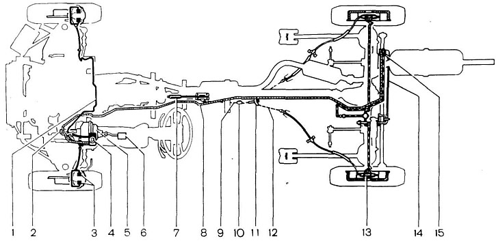
Fig. 54. Brake system diagram:
1 - front brake circuit; 2 - master cylinder of the hydraulic brake system; 3 - front disc brake cylinders; 4 - brake hydraulic fluid reservoir; 5 - vacuum booster; 6 - brake pedal; 7 - parking brake lever; 8 - rear brake circuit; 9 - front parking brake cable, 10 - front cable guide roller; 11 - rear cable equalizer; 12 - rear night brake cable; 13 - rear drum brake wheel cylinder; 14 - pressure regulator torsion lever; 15 - pressure regulator.
Before servicing the brake system, clean each brake from dirt, rinse with warm water and dry with compressed air. Do not use gasoline, diesel fuel, trichloroethylene or other types of solvents, as they corrode the cuffs and seals of the hydraulic cylinders.
The surfaces of the friction linings of the brake shoes must be clean, without traces of dirt and grease. Clean dirty linings with a wire brush and wash with white spirit. If you find grease on the linings, check for grease or brake fluid leaks through the seals and eliminate the faults. During maintenance, protect the brakes from oil.
Brake fluid reservoir
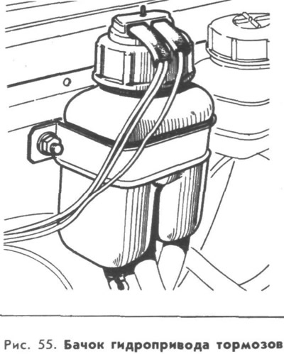
Every 10,000 km mileage, check the fluid level in the tank (Fig. 55), which with the cap installed should reach the lower edge of the filler neck. You should add "Rosa" or "Tom" brake fluid. By pressing the pusher on the tank cap, check the correct operation of the fluid level indicator - with the ignition on, the control lamp should light continuously.
After 5 years of operation, it is recommended to replace the brake fluid with fresh one.
Flexible brake hoses
Every 10,000 km, starting from 30,000 km of run, check the condition of the brake hoses. If small cracks are found on the outer casing or swelling appears when pressing the brake pedal, replace the hose with a new one.
Front disc brakes
Every 10,000 km mileage, check the condition of the brake shoe linings. Replace the shoes if the thickness of the friction linings 1 (Fig. 56) decreases to 1.5 mm. If you are not removing the shoes for replacement, mark them so that you can put them back in place during assembly. To remove the brake shoes 7, remove the cotter pins 4 and the pins 10 with springs 2 and 5.
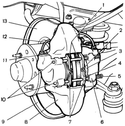
Fig. 56. Front disc brake:
1 - brake pads; 2 - spring; 3 - brake cylinder piston; 4 - cotter pin; 5 - spring; 6 - brake cylinder; 7 - brake pads; 8 - support; 9 - brake disc casing; 10 - brake shoe mounting pins; 11 - nipple; 1 2 - connecting tube; 13 - brake disc.
Before installing the pads, make sure that the brake disc 13 is not damaged or has very deep scratches. If the disc is worn to a thickness of less than 9 mm, replace it with a new one.
To install the pads, move the pistons 3 as far as possible inside the cylinders 6. Make sure that the rubber protective seals of the pistons are in their seats and are not damaged. Replace the seals if necessary. When moving the pistons inside the cylinders, the fluid level in the reservoir increases. To avoid overflow, remove the cover and promptly collect the required amount of fluid. Then install the pads 7, insert the pins 10 with the springs 5, install the cotter pins 4 and the springs 2.
After replacing the pads, there is no need to bleed the brake system. Bleeding is only necessary after disassembling the caliper 8 or if there is air in the brake system and is carried out through the nipple 11.
The adjustment required to compensate for wear of the linings is made automatically.
Rear drum brakes
Every 20,000 km check the condition of the rear brake pads, for which:
- place the car on a level surface and place chocks under the wheels;
- release the parking brake and loosen the rear wheel mounting bolts;
- install the jack and remove the wheel;
- remove the brake drum 2 (Fig. 57), for which unscrew the two bolts 1, insert them into the technological holes "A" and tighten until the drum separates.
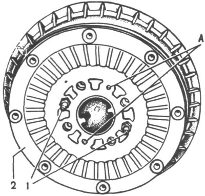
Fig. 57. Brake drum:
1 - bolts; 2 - brake drum; A - technological holes.
Removing and installing the brake drum is significantly simplified if the auto preparation "Unisma-1" is applied to the gap between the hub and the drum, leaving it for 10-15 minutes after application.
Check the condition of the brake shoes 2 (Fig. 58) with friction linings 1 and the working surface of the brake drum. If the shoes are damaged or deformed, which prevents uniform contact of the linings with the drum and reduces braking efficiency, replace them with new ones. Replace the shoes also if the thickness of the linings decreases to 2 mm. Replace the shoes only in pairs. The gap between the shoes and drums is restored automatically as the linings wear out.
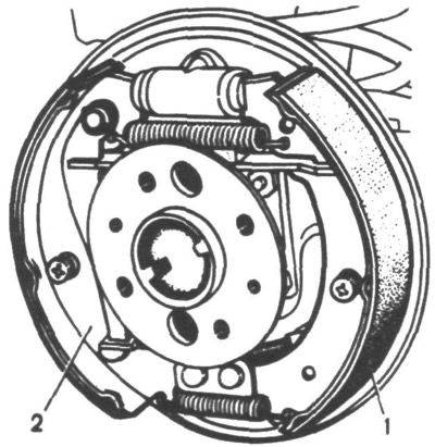
Fig. 58. Rear brake with drum removed:
1 - friction lining; 2 - brake shoe.
If deep scratches have formed on the working surface of the drum or the surface has become excessively oval, the drums must be bored and ground at a service station. Before installing the drum, lubricate the seat belt with a thin layer of graphite grease.
When checking the rear brakes, do not forget to pay attention to the condition of the protective rubber boots of the brake cylinders.
Bleeding the brake system
Increased brake pedal travel and its "softness" indicate the presence of air in the brake system, which significantly reduces the effectiveness of the brakes. Bleed the brake system together. During the bleeding process, to eliminate the influence of the pressure regulator, do not hang the rear of the car.
Remove air from the system by bleeding the brake cylinders sequentially, first the rear circuit, then the front, as follows:
1. Unscrew the reservoir cap (Fig. 55) and add brake fluid, bringing its level to the norm.
2. Remove the protective caps from fittings 11 (Fig. 56) and 1 (Fig. 59) and wipe the fittings with a clean cloth. Attach the rubber hose from the accessory kit to the end of the fitting and immerse the other end of the hose in a clean transparent container partially filled with brake fluid,
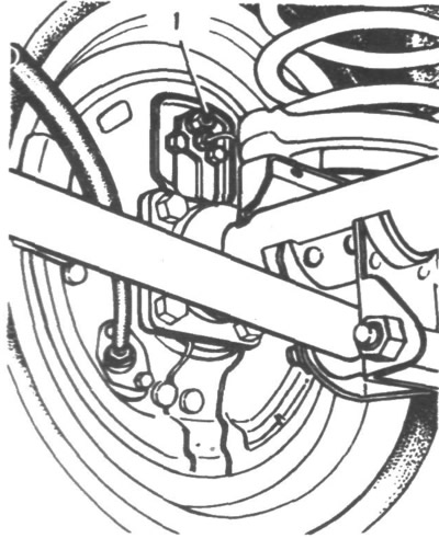
Fig. 59. View of the drum brake shield from the rear axle:
1 - nipple for bleeding the rear brake hydraulic system.
3. Press the brake pedal sharply 3-5 times with an interval of 2-3 seconds between presses and, holding the pedal pressed, unscrew the nipple by 1/2-3/4 of a turn, forcing the fluid and air out of the system through the hose into the container by pressing the pedal. After the brake pedal reaches the extreme forward position and the fluid flow through the hose stops, tighten the nipple.
4. Repeat step 3 until no more air bubbles come out of the hose. Keeping the brake pedal depressed, tighten the nipple until it stops, remove the hose, wipe the end of the nipple dry and put the protective cap on it.
During the bleeding process, make sure that the fluid level in the tank is sufficient. After bleeding the system, restore the required maximum level in the tank.
It is not recommended to use the fluid released from the brake system during bleeding.
If the brake system is not bled well enough, then when you press the brake pedal at the end of its travel, you will feel an increased "softness", the greater the more air remains in the system. If it is impossible to completely remove air through one nipple, repeat the bleeding simultaneously through two nipples for each pair of wheels.
Replacing brake fluid
To replace the brake fluid with fresh one:
- place the car on a lift or inspection pit;
- remove the protective caps from the fittings, put rubber hoses on the fittings, and lower the other ends into transparent containers;
- unscrew the nipples by 1/2-3/4 of a turn and ask the assistant to sharply press the brake pedal and smoothly release it. In this way, the fluid from the system will flow into the vessels. As the fluid stops flowing, tighten all the nipples in sequence. Drain the fluid from the vessels, pour fresh brake fluid into the reservoir and unscrew the nipples;
- again, ask your assistant to press the brake pedal sharply and release it smoothly, and also monitor the fluid level in the reservoir, not allowing the bottom to become "dry";
- when liquid appears in the vessel, tighten all the fittings in sequence;
- bleed the brake system in accordance with the procedure described above.
Adjusting the brake pedal free travel
The free travel of the brake pedal with the brake system in good condition and the engine not running should be 3-5 mm. Adjust it by moving the switch 6 (Fig. 60) of the brake light together with the buffer 4 with the nut 5 previously unscrewed. After completing the adjustment, tighten the nut 5.
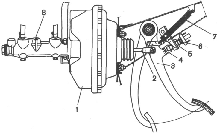
Fig. 60. Brake pedal:
1 - vacuum booster; 2 - pusher; 3 - brake pedal; 4 - brake light switch buffer; 5 - stop screw nut; 6 - brake light switch; 7 - pedal release spring; 8 - master cylinder of the brake hydraulic system.
Vacuum brake booster
Every 30,000 km check the performance of the vacuum booster, for which:
- press the brake pedal 5-6 times with the engine off;
- keeping the brake pedal depressed, start the engine. If the booster is in good working order, the brake pedal should "go forward" after starting the engine. If this does not happen, check the tightness of the hose connections to the intake pipe and to the booster, since loose fasteners cause air to leak in and dramatically reduce the efficiency of the booster. If the problem persists after this, contact a service station.
Pressure regulator
Every 30,000 km check the performance of the pressure regulator, for which:
- place the car on a lift or inspection pit;
- clean the regulator and cover from dirt;
- carefully remove the cover, remove any remaining grease and clean the "torsion arm - regulator piston" connection;
- ask an assistant to press the brake pedal sharply. If the pressure regulator is working properly, the protruding part of the piston will move relative to the housing, twisting the torsion lever;
- repeat the operation 2-3 times and, after making sure that the regulator is working properly, add 5-6 g of fresh DT-1 grease and put on the cover.
If the piston does not move relative to the body, contact a service station.
Parking brake
Every 20,000 km mileage, and on a new car after the first 2000-3000 km, check and, if necessary, adjust the stroke of the parking brake lever.
Correct adjustment of the parking brake ensures reliable operation of the vehicle's braking system. If the vehicle does not brake with the parking brake on a slope of up to 30% when the lever is moved by 4-5 teeth of the sector, adjust the lever stroke with a tensioner. To adjust:
- move the lever to its lowest position and lift it up by two sector teeth;
- loosen lock nut 2 (Fig. 61) and, by turning adjusting nut 1, tighten the cable;
- tighten lock nut 2 and check whether the car remains in the braked state when the lever is moved 4-5 teeth.
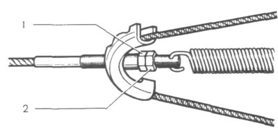
Fig. 61. Adjusting the travel of the parking brake lever:
1 - adjusting nut; 2 - lock nut.
To prevent the brake shoes from freezing to the drums after driving on wet roads with sudden temperature fluctuations, do not tighten the parking brake when parking the car in an open area or in an unheated garage without "drying" the brakes by braking smoothly when moving to the parking space.