
Brake drive
The drive of working brakes is hydraulic, foot. The main brake cylinder is two-cavity, has two coaxial pistons.
A pressure regulator is connected in series to the hydraulic drive of the rear wheels, which reduces the pressure in the hydraulic drive with a decrease in the load on the rear axle, which prevents «yuz» rear wheels and thereby increases the stability of the vehicle. The brake drive of the VAZ-2103 car is additionally equipped with a vacuum booster and an alarm about the insufficient level of brake fluid in the master cylinder reservoir.

Open large image in new tab »
1. Front wheel brake. 2. Front circuit piping. 3. Master brake cylinder. 4. Brake fluid reservoir 5. Vacuum booster (2103). 6. Rear circuit piping. 7. Regulator drive lever. 8. Rear wheel brake. 9. Pressure regulator. 10. The union of a contour of back brakes. 11. Fitting (two) front brake lines. 12. Vacuum hose fitting. 13. Tip. 14. Tip valve. 15. Valve spring. 16. Thrust spring cup. 17. Nutrient tank. 18. Cork reflector. 19. Moving contact. 20. Hose. 21. Pusher. 22. Terminal cover. 23. Fixed contacts (two). 24. Stopper of the nutrient tank. 25. Float. 26. Diaphragm. 27. Valve body 28. Amplifier housing cover. 29. Piston. 30. Valve support sleeve. 31. Front support cup. 32. Rear support cup. 33. Air filter. 34. Valve lifter. 35. Retractable spring. 36. Stoplight switch. 37. Brake pedal. 38. Return spring. 39. Protective cap. 40. Valve spring. 41. Valve. 47. Self-clamping gland. 43. Pressure and retaining rings. 44. Thrust plate. 45. Rod base buffer 46. Axle bushing. 47. Pedal bracket. 48. The axis of the pedals. 49. Pedal bushing. 50. Return spring. 51. Amplifier case. 52. Piston drive rod. 53. Self-clamping gland. 54. Clip. 55. Remote cup. 56. O-ring. 57. Front brake piston. 58. Locking screw. 59. Thrust washer. 60. Sealant. 61. Rear brake piston. 62. Spacer ring. 63. Compression spring. 64. Master cylinder housing. 65. Return spring. 66. Cork. a - reporting channel; b - annular gap; in — an inlet air window; g - an annular gap; e - channel; e - hole; A - vacuum cavity; B is the atmospheric cavity.
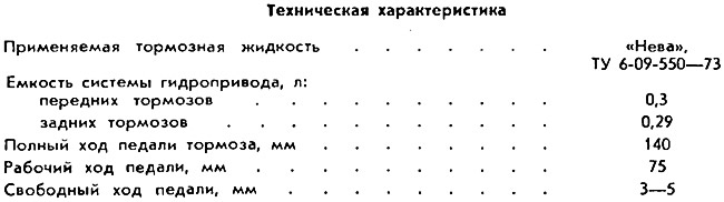
The main components of the hydraulic brake drive are: brake pedal, vacuum booster 5 (only for VAZ-2103), brake master cylinder 3, brake fluid reservoir 4, pipelines, pressure regulator 9 and wheel cylinders for front and rear brakes.
The brake pedal is mounted on the same axle 48 with the clutch pedal. The axis 48 is fixed in the holes of the cheeks of the bracket 47 and rotates in two polyamide bushings 49. The brake pedal is constantly pulled to its original position by the spring 35 and in the free state abuts against the tip of the brake light switch 36.
The free play of the brake pedal is regulated only on the VAZ-2101 and VAZ-2102 by changing the position of the brake light switch.
The free play of the brake pedal on the VAZ-2103 is not regulated during operation, but is provided during assembly.
The piston pusher of the main brake cylinder is connected to the brake pedal (for VAZ-2101 and 2102) or tappet 34 brake booster valves (for VAZ-2103).
The main brake cylinder is attached to the vertical shelf of the bracket 47 (VAZ-2101 and 2102) or vacuum brake booster together with brake master cylinder (VAZ-2103). When fastening, a rubber gasket is installed between the housing cover and the mating plane of the bulkhead.
The vacuum brake booster consists of three main components: the body 51 of the booster, the cover 28 and the body 27 of the valve with the diaphragm 26, dividing the booster into two cavities - vacuum A and atmospheric B. The body 27 of the valve acts as a piston moving in the body 51 of the booster. Diaphragm 26 serves as a seal between the valve body and the amplifier body.
In the opening of the hub of the valve body there are: the base of the stem, the rubber buffer 45, the valve 41 and the foam air filter 33. The rubber valve 41 is assembled on the pusher 34. The fixed shoulder of the valve, constantly pressed by the return spring 38 through the support cup 31, creates a reliable seal with the body wall. The movable shoulder of the valve 41, reinforced with a steel washer, is put on the sleeve 30 with a support rim and is constantly pressed out by the internal conical spring 40.
The spherical head of the pusher 34 enters the piston seat 29 and is fixed there by stamping the piston neck at three points.
The assembled valve is inserted into the body 27 and fixed in it with a thrust plate 44. The plate 44 is kept from falling out during the operation of the amplifier by the diaphragm 26.
The valve body, together with the return spring 50, is inserted into the body 51 of the amplifier and is closed with a cover 28, which is locked by turning the cover until its edges are planted under the locking protrusions of the body of the amplifier. The connector of the body and the cover seals the shoulder of the diaphragm clamped between them.
The exit of the valve body hub from the opening of the cover 28 is sealed with a self-clamping gland 42. The part of the valve body hub that extends during operation is protected by a rubber corrugated cap 39.
The output of the rod 52 from the amplifier housing is sealed with a self-clamping gland 53, reinforced with a steel clip 54. The gland is evenly pressed against the wall of the socket by a remote cup 55, creating the necessary tightness of the amplifier housing.
Before connecting the main brake cylinder to the amplifier, the head of the rod 52 is adjusted by the amount of protrusion beyond the plane of the body 51, equal to 1.05-1.25 mm. The amount of protrusion determines the free travel of the brake pedal
A sleeve for attaching a vacuum hose is welded into the front wall of the amplifier housing. A rubber valve 14 with a compression spring 15 is mounted in the tip 13, which prevents the combustible mixture from entering the vacuum cavity of the amplifier. A flexible hose connects the vacuum booster to the engine intake pipe.
The main brake cylinder has a through cylindrical hole, machined with great precision and high surface finish of the mirror. Five holes are made in the top of the cylinder to communicate the cavity of the hydraulic drive of the front brakes with the supply reservoir 17, the wheel cylinders of the front brakes and the rear brake pressure regulator.
From below, locking screws 58 are screwed into the threaded holes of the body, limiting the movement of pistons 57 and 61. Copper sealing gaskets are installed under the heads of the locking screws.
The main brake cylinder contains: piston 57 of the hydraulic drive of the front brakes with a sealing ring 56, a seal 60 of the piston head and a spacer ring 62, a piston 61 of the hydraulic drive of the rear brakes with seals 60, a thrust washer 59 and a spacer ring 62. The seal 60 of the piston head is constantly pressed by the spring 63, the front end of which rests through the cup against the return spring 65. In the lower part of the piston 57 there is a longitudinal groove for the locking screw. The length of the groove determines the maximum stroke of the piston. The piston head has a through radial hole for the passage of brake fluid.
The central drilling of the piston shank, two opposite holes in the neck of the annular groove and the labyrinth formed by the surfaces of the seal, the spacer ring 62 and the piston are designed for the passage of brake fluid under various braking conditions.
The seal 60 of the piston head 61 is pressed by the spring 63. The piston itself is constantly pressed in a free state to the rearmost position by the return spring 65.
The design of the piston 61 is similar to that of the piston 57, except for the rear part, in which, instead of the sealing ring 56, a seal 60 with a toroidal sealing surface is installed, due to which the seal withstands high specific pressures of the brake fluid.
The lower groove of piston 61 is shorter than that of piston 57 because less brake fluid is required to actuate the rear brakes.
Both cavities of the master brake cylinder are connected by hoses to the cavities of the nutrient tank 17 (VAZ-2103) or two separate tanks (VAZ-2101 and 2102).
Nutrient tank of the car VAZ-2103 (and other car models) made of translucent polyethylene, which facilitates visual control of the brake fluid level. The volume of the tank is divided by a partition into two cavities: the right cavity (along the car) - for backup power supply of the hydraulic drive of the front brakes, the left cavity - for backup power supply of the hydraulic drive of the rear brakes.
The filler neck of the tank is closed with a plug 24, which has a device for controlling the level of brake fluid in the tank, which includes a float 25 and a movable contact 19 mounted on its rod. The foam propylene float, floating in the brake fluid, descends when its level drops and at a certain moment closes the control lamp circuit with a moving contact, which lights up with a constant light. Fixed contacts 23 are riveted to the bottom of the plastic housing. Power is supplied to them through the terminals of the plastic cover 22.
A pusher 21 is inserted into the central hole of the terminal cover, which is used to check the operation of the test lamp circuit (with a full tank, pressing the pusher, drown the rod with the float until the control lamp circuit is closed by a moving contact - the lamp should light up). When assembled, the body is held in plug 24 by two latches.
Models VAZ-2101 and VAZ-2102 do not have devices for controlling the level of brake fluid.