




Contents: Steering clearances ↓ Front wheel hub bearings ↓ Checking the condition of the front…↓ Tires ↓
Steering clearances
Every 10,000 km mileage, and on a new car after the first 2000-3000 km, check the free play (play) of the steering wheel, which, with normal clearances in the steering and the position of the wheels corresponding to the movement of the car in a straight line, should not exceed 18-20 mm (approximately 5°) when measured along the wheel rim.
If the free play exceeds this value, check the steering:
1. Make sure that the front wheel bearing clearances are adjusted correctly and that the tire pressure is normal.
2. Turn the steering wheel to one side and the other to check for knocks in the joints, steering gear and connections. Check and, if necessary, tighten the fastening parts of the steering arm 7 (Fig. 46), the steering gear housing, the pendulum arm brackets 9 and the steering column shaft.
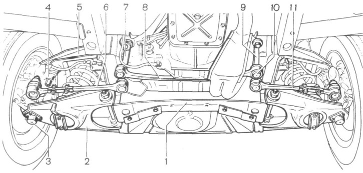
Fig. 46. Front suspension and steering:
1 - crossbar; 2 - lower arm; 3 - lower arm ball joint; 4 - ball joint of the upper arm; 5 - upper arm; 6 - left lateral steering rod; 7 - bipod; 8 - middle steering rod; 9 - pendulum lever; 10 - ball joint; 11 - right lateral steering rod.
3. While rocking the steering wheel, check by touch that there are no gaps in the ball joints 10 of the steering rods.
4. Check the condition of ball joints 3 and 4, joints of arms 2 and 5 of the front suspension and make sure they are in good working order.
5. Correct any detected faults and check the free play of the steering wheel.
If the steering wheel free play is greater than the permissible value, check and adjust:
- clearance in the worm bearings, which is determined by the axial movement of the steering shaft when the steering wheel is turned a small angle to the left and right; the gap is adjusted by reducing the number of gaskets 3 (Fig. 47) between the crankcase and the thrust bearing cover to a value at which the shaft will rotate easily without moving in the axial direction;
- lateral clearance between the roller and the worm. To do this, align the mark "A" on the shaft with the mark "B" on the housing with the position of the wheels corresponding to the rectilinear movement of the car (neutral position). The clearance is determined in the neutral position by swinging the pitman arm by its head with the rods disconnected from it and is adjusted by tightening screw 1 with nut 2 loosened. After adjustment, tighten nut 2. There should be no lateral clearance in the engagement within the steering wheel rotation of 30° to the right and left from the neutral position.
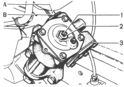
Fig. 47. Adjusting clearances in the steering mechanism:
1 - screw; 2 - nut; 3 - adjusting linings; A and B are marks.
Front wheel hub bearings
Every 10,000 km mileage, and on a new car after the first 2000-3000 km, check and, if necessary, adjust the clearances in the front wheel hub bearings.
To check the gaps:
- remove the wheel (see section "Wheel replacement");
- remove cap 5 (Fig. 48), secure the indicator to hub 2 and move its leg to the end of the steering knuckle journal;
- move the hub towards you with your hands while rotating it until the indicator shows a constant reading and set the arrow to zero;
- measure the clearances in the hub bearings by moving the hub axially away from you while simultaneously rotating it until the indicator shows a constant reading. If the indicator readings exceed 0.15 mm, adjust the clearances in the bearings as follows:
[The original is posted on Internet resource: VAZbook.ru]
- remove the indicator, unscrew nut 4 and replace it with a new one;
- tighten nut 4 to 20 Nm (2 kgf·m), rotating the hub in both directions;
- loosen the nut and tighten it again to a torque of 7 Nm (0.7 kgf·m), then unscrew it by 20-25°;
- measure the bearing clearances with a dial indicator. If the clearances exceed 0.08 mm, repeat the adjustment. If the clearances are within 0.02–0.08 mm, lock nut 4 by pressing the notches on the nut flange into the grooves on the end of the steering knuckle journal;
- remove the indicator, install cap 5, secure the wheel, remove the car from the jack and finally tighten the wheel mounting bolts.
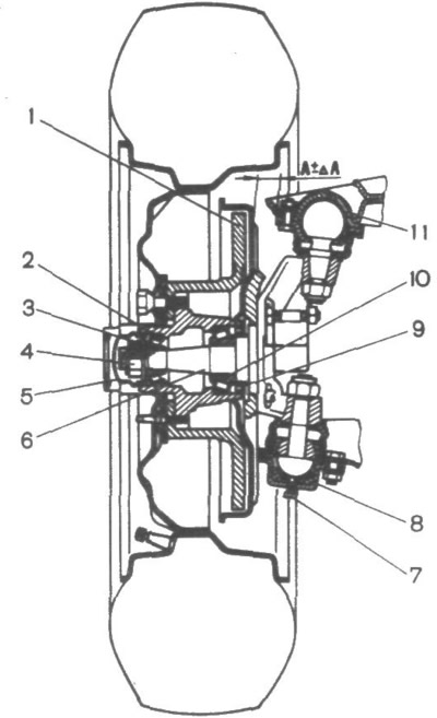
Fig. 48. Front wheel:
1 - brake disc; 2 - hub; 3 - outer roller bearing; 4 - hub mounting nut; 5 - cap; 6 - steering knuckle; 7 - cork; 8 - lower arm ball joint; 9 - oil seal; 10 - inner roller bearing; 11 - ball joint of the upper arm.
Every 20,000 km mileage, replace the consistent grease in the bearings. To replace the grease:
- remove the wheel and brake caliper;
- remove cap 5, unscrew nut 4 and carefully, so as not to damage oil seal 9, remove hub 2 assembled with brake disc 1 from steering knuckle 6;
- wash the inner cavity of the hub and bearings 3 and 10 with kerosene;
- place 40 g of fresh consistent grease LITOL-24 into the bearing separators and into the hub cavity between the bearings;
- install hub 2 on steering knuckle 6, tighten new nut 4 and adjust bearing clearances as described above;
- place 25 g of grease into cap 5 and install it on the hub.
Checking the condition of the front suspension ball joints
Before checking the condition of the ball joints, find out:
- is there any deformation of the levers, buffer brackets, front body pillars and lower arm axles;
- serviceability of protective rubber covers.
To check the condition of the ball joint 11 of the upper arm, remove the wheel and install the suspension on a stand. Sharply rocking the wheel hub, determine the total clearance 2DA using an indicator attached to the ball joint housing. If it is more than 0.8 mm, replace the ball joint.
To determine the condition of the ball joint 8 of the lower arm, remove the wheel and install the hub on a support. Measure the distance from the lower edge of the support housing to the surface of the pin through the lubrication hole closed by plug 7. If this distance exceeds 11.8 mm, replace the support.
Tires
Every 500 km check the air pressure in the tires, including the spare tire, with a pressure gauge.
It is recommended to periodically check the pressure gauge at a service station.
Each time you check the tire pressure, check at the same time with a soap solution applied to the valve inlet to see if there is any air leakage through the inner tube valve core. If there is an air leak, indicated by the appearance of a soap bubble, tighten the valve core with the valve cap or replace it with a new one. If there is a constant drop in pressure with a functioning valve core, remove the tire, check and repair the inner tube or replace it with a new one.
To avoid disturbing the wheel balance, before dismounting, make a mark with chalk on the tire opposite the inner tube valve and install the tire in place using this mark during installation. We recommend dismounting the tire with a completely deflated inner tube and ensuring that the part of the tire opposite the section being mounted is in the recess of the wheel rim. Dismount and mount the tire using a tire mounting blade and a combination wheel mount key. The distance between them when gripping the tire bead should not exceed 150 mm.
After installing new tires, be sure to have the wheel balancing checked at a service station.
The vehicle may also be equipped with 165/82R13 IYA-170 radial textile cord tires and 175/70R13 IN-251 radial metal cord tires. As a rule, tires of the same model and size must be installed on all wheels. In operation, it is allowed to install radial textile cord tires on the front wheels and radial metal cord tires on the rear wheels. It is not allowed to install tires of different design, model, or size on one axle.
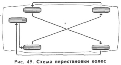
Every 10,000 km to ensure uniform wear of the tires, rotate the wheels as shown in Fig. 49.
If abnormal vibrations (vibrations) of the vehicle occur while driving, check the wheel balancing at the service station.