




Contents: Removal and inspection ↓ Installation ↓
Warning! Before performing work, read the precautions for repairing the engine management system (see "Precautions when repairing the engine management system").
To complete the work you will need:
- multimeter (in voltmeter mode, ohmmeter with a measurement range from 100 Ohm to 10 kOhm);
- thermometer (with a change limit of at least 100°C);
- a small heat-resistant container with a capacity of about 0.5 l for water;
- about 0.3 l of water heated to boiling point.
Tip: The thermometer can be replaced with a digital multimeter with a thermometer mode.
Removal and inspection
1. Drain the coolant (see "Coolant - replacement").
2. Remove the air filter (see "Air filter - removal and installation").
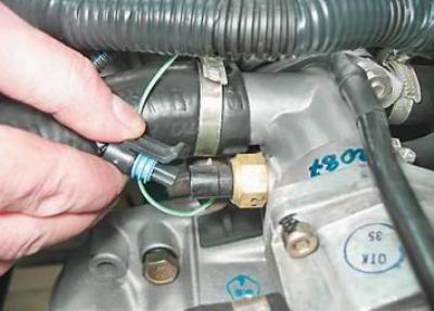
3. Release the wiring harness connector retainer and disconnect the connector from the sensor.
4. Connect the negative probe of the voltmeter to the engine ground.
5. Turn on the ignition and use a voltmeter to measure the voltage at terminal A of the wiring harness connector (the terminal designations are marked on the wiring harness block).
Note: The voltage at the terminal must be at least 12 V. If the voltage does not reach the connector or is less than 12 V, the battery is discharged, the power supply circuit is faulty, or the ECU is faulty.
Warning! After completing the voltage measurement, turn off the ignition.
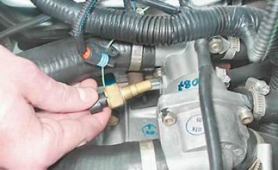
6. Key by 19 mm we unscrew the temperature sensor and remove it from the thermostat housing. The connection of the sensor with the thermostat is sealed with a copper washer.
7. Connect the ohmmeter to the sensor terminals.
8. Fill the container with boiling water, immerse the working part of the sensor in the water and record the readings of the device at a temperature of about 100°C. As the water cools, measure the resistance of the sensor at temperatures of: 90, 80, 70, 60, 50, 45, 40, 35, 30, 25 and 20°C.
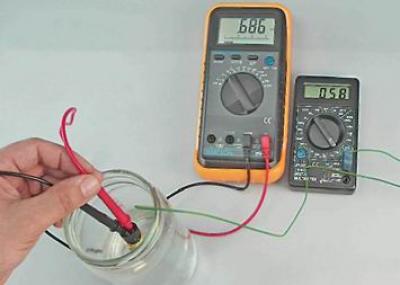
If conditions allow, readings can be taken at a lower temperature. The resistance of a working sensor should be close to the data specified in the table:
|
Coolant temperature,°C |
Coolant temperature sensor resistance, Ohm |
|
100 |
177 |
|
90 |
241 |
|
80 |
332 |
|
70 |
467 |
|
60 |
667 |
|
50 |
973 |
|
45 |
1188 |
|
40 |
1459 |
|
35 |
1802 |
|
30 |
2238 |
|
25 |
2796 |
|
20 |
3520 |
|
15 |
4450 |
|
10 |
5670 |
|
5 |
7280 |
|
0 |
9420 |
We replace the faulty sensor.
Installation
1. Install the sensor in reverse order.
2. Fill the engine cooling system with liquid.
3. Start the engine and make sure there are no coolant leaks from under the sensor. If necessary, tighten the sensor into the thermostat housing.
Recommendation: If this method does not eliminate the leak, reinstall the sensor, applying heat-resistant sealant to its threaded part or replace the copper washer.