
Warning! Before starting work, read the precautions for repairing the engine management system (see "Precautions when repairing the engine management system").
You will need a multimeter to do the job (in voltmeter mode).
Removal and inspection
1. We prepare the car for work (see "Preparing the car for maintenance and repair").
On engines 2112, 21124 and 21114 remove decorative trim (see "Decorative overlay of the engine - removal and installation").
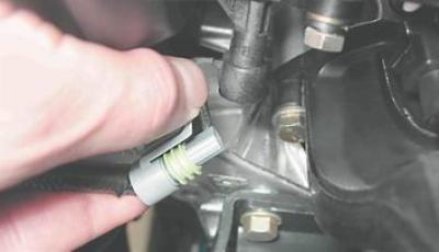
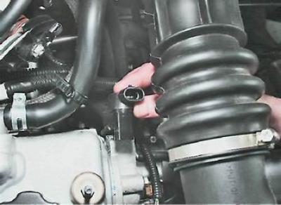
2. Having released the latch, disconnect the wire block from the camshaft position sensor on the 8-valve engine.
Note. On a 16-valve engine, the operation is as follows:
3. Connect "negative" voltmeter probe to "mass" (to the car body).
4. Turning on the ignition, use a voltmeter to measure the supply voltage at terminal A of the wiring harness block (terminal designations are made on the block).
Comment. The voltage at the output must be at least 12 V. If the voltage is not supplied to the block or it is less than 12 V, then the battery is discharged, the power circuit is faulty or the computer is faulty.
On engines 2112 and 21124:
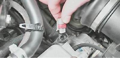
5. socket wrench by 10 mm Remove the two screws securing the camshaft position sensor.
6. We remove the sensor from the hole in the rear cover of the timing belt.
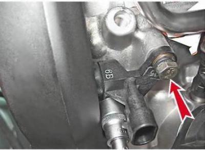
On engines 2111 and 21114:
5. socket wrench by 10 mm Loosen the camshaft position sensor mounting bolt.
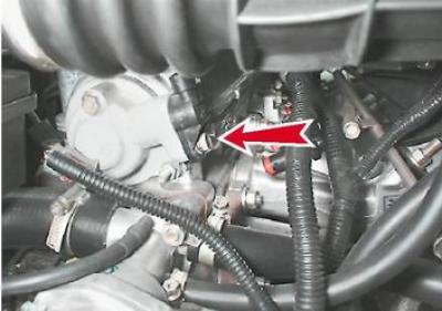
6. Remove the camshaft position sensor from the cylinder head plug hole.
7. Remove the rubber sealing ring from the sensor. Replace damaged ring.
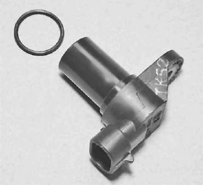
Advice. You can verify that the camshaft position sensor is faulty by replacing it with a known good one
Installation
Install the camshaft position sensor in reverse order.