
Removing
1. We prepare the car for work and disconnect the terminal from the negative terminal of the battery (see "Preparing the car for maintenance and repair").
2. Using a Phillips screwdriver, unscrew the three screws securing the left lining of the instrument panel console.
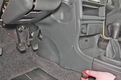
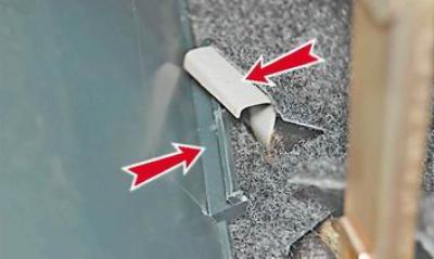
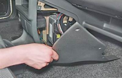
3. Remove the trim, removing the protrusion in its lower part from the body bracket.
4. Using a Phillips screwdriver, unscrew the five screws securing the right trim of the instrument panel console.
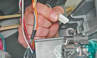
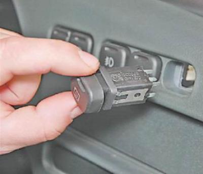
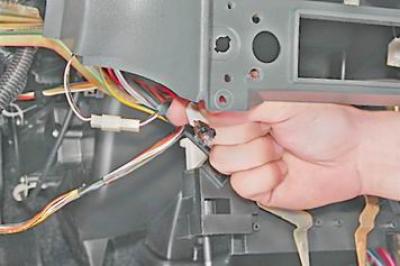
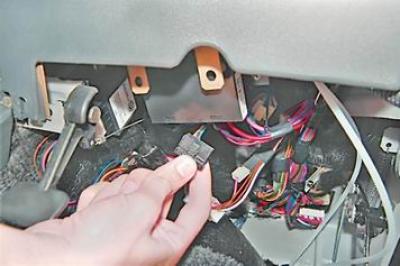
5. Disconnect the wiring harness block from the cigarette lighter.
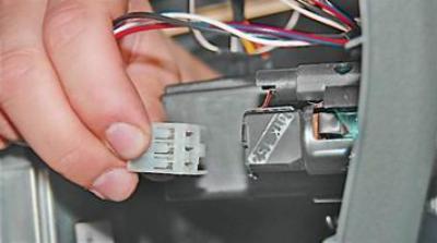
6. Disconnect the wire block from the cigarette lighter backlight.
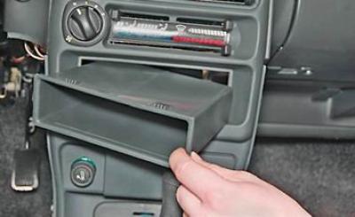
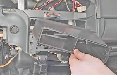
7. Pushing out from the inside, we take out a niche for small items.
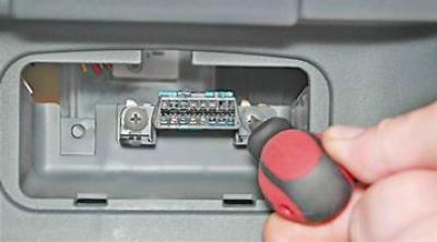
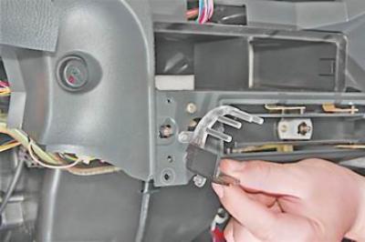
8. Using a Phillips screwdriver, unscrew the two fastening screws and sink the diagnostic connector block into the panel.
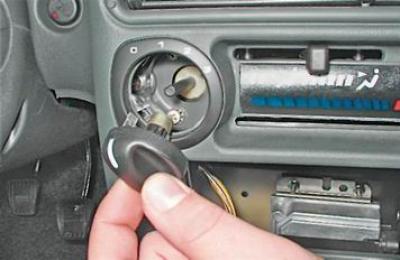
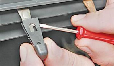
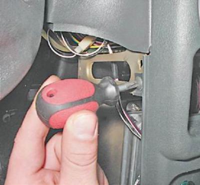
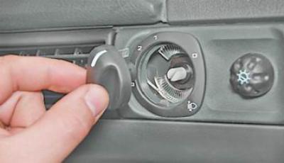
9. Pulling it towards you or prying it with a screwdriver, remove the handle of the heater electric fan switch.
10. With a narrow slotted screwdriver inserted between the lever and the handle, remove the handle from the lever.
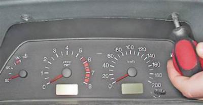
11. Using a Phillips screwdriver, unscrew the two screws above the instrument panel.
12. We also unscrew the two screws under the instrument panel.
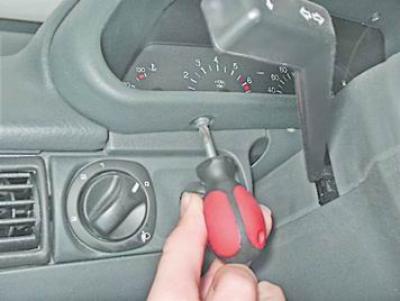
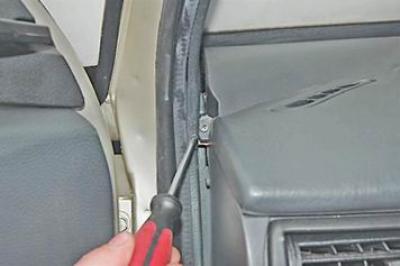
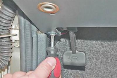
13. Using a screwdriver, remove the plug and unscrew the screw of the upper fastening of the instrument panel lining.
14. Turn off two screws (the second is on the right side of the lining) bottom mount pad.
15. Slightly move the trim away from the instrument panel.
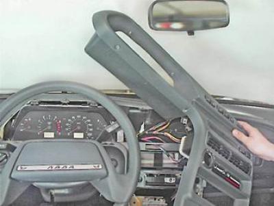
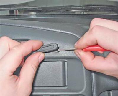
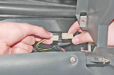
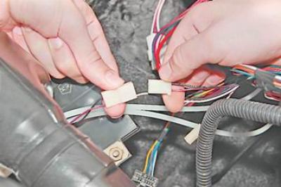
16. Marker (or otherwise) mark the order of connecting the wiring harness pads to the switches.
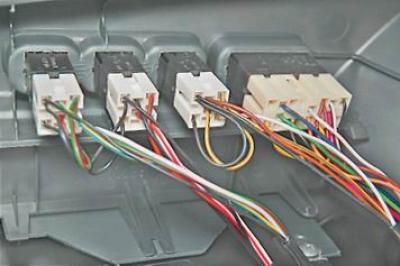
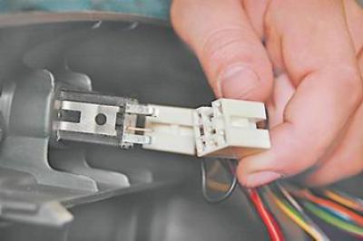
17. Disconnect the wiring harness pads from the switches.
Note: If it is necessary to replace the instrument panel lining, remove the switches from it.
18. Remove the instrument panel (see "Instrument panel - removal and installation").
19. Turn off the bolts of the steering column bracket and lower the column down (see "Steering column - removal and installation").
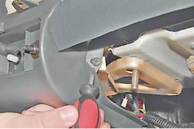
20. Using a Phillips screwdriver, unscrew the two screws securing the bracket to the panel.
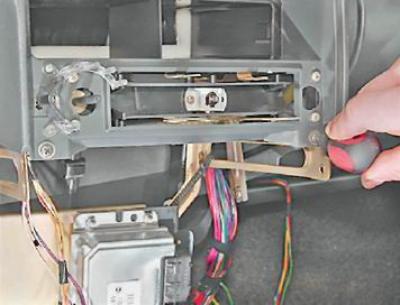
21. Key by 8 mm unscrew the two screws securing the bracket to the right cross member...
... as well as two self-tapping screws for the lower mounting of the bracket.
22. We remove the bracket with the control unit and the relay and fuse box to the side.
23. Using a Phillips screwdriver, unscrew the self-tapping screw for fastening the light guide and remove it from the instrument panel.
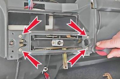
24. Using a Phillips screwdriver, unscrew the four screws securing the heater control unit and sink it into the panel.
25. From the inside of the panel, turning 90°, remove the lamp holder for the backlight of the heater electric fan switch handle.
26. Having pressed the latch on the right side of the air duct, we take it out of the panel.
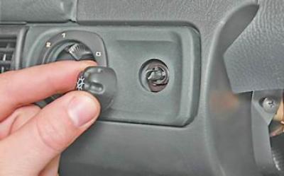
27. Pulling towards you, remove the headlight hydrocorrector knob.
28. In the same way, remove the instrument backlight control knob.
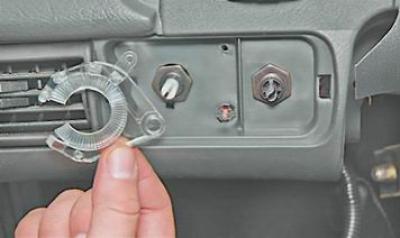
29. Prying with a screwdriver, remove the decorative insert of the instrument panel.
30. In order not to damage the light guide, use a Phillips screwdriver to unscrew its fastening screw and remove it from the panel.
Warning! The light guides for the illumination of the handles of the heater electric fan switch and the headlight hydrocorrector are not interchangeable.
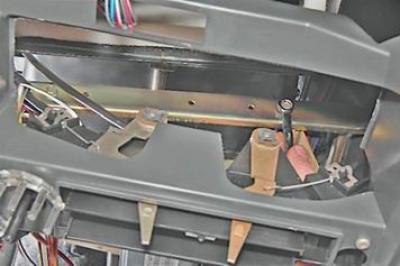
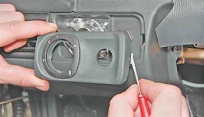
31. socket wrench by 21 mm (candle key), or with pliers with narrow jaws, unscrew the hydraulic corrector fastening nut (1) and push it into the dashboard.
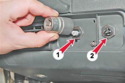
32. In the same way, unscrew the nut for fastening the instrument backlight control (2) (see photo above).
33. Turning the bulb holder by 90°, remove the hydrocorrector backlight from the panel.
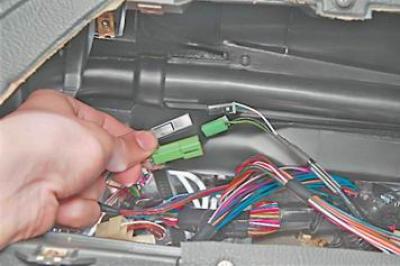
34. We disconnect the pads of the wiring harness for the instrument backlight regulator.
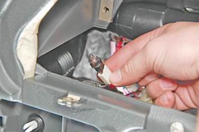
35. Disconnect the two blocks of the immobilizer sensor wires.
36. Disconnect the wiring harness block from the immobilizer unit.
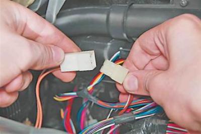
37. Disconnect the wiring harness pads for the glove box lighting lamp.
38. Disconnect the wiring harness pads of the portable lamp socket.
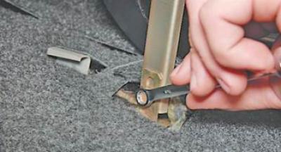
39. Using a Phillips screwdriver, unscrew the two screws of the upper panel mount (the second screw is on the right side).
40. We turn off two self-tapping screws of the lower fastening of the panel.
41. Using a Phillips screwdriver, unscrew the self-tapping screw securing the panel to the left cross member.
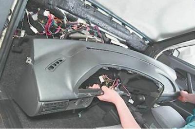
42. Remove the instrument panel.
Installation
Install the instrument panel in reverse order.