




- electronic control unit;
- sensors:
- 1. crankshaft position sensor;
- 2. camshaft position sensor;
- 3. throttle position sensor;
- 4. knock sensor;
- 5. coolant temperature sensor;
- 6. mass air flow sensor;
- 7. vehicle speed sensor;
- 8. oxygen concentration sensor;
- actuators:
- 1. main relay;
- 2. fuel pump relay;
- 3. injectors;
- 4. Ignition coil or ignition module [The ignition module was installed on cars of the first years of production.];
- 5. idle speed control;
- 6. Cooling system electric fan relay;
- 7. Engine management system malfunction indicator lamp;
- 8. purge valve of the adsorber;
- connecting wires;
- diagnostic connector block.
The engine management system also integrates:
- car anti-theft system;
- speedometer;
- tachometer.
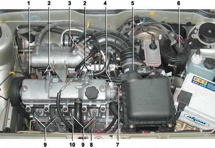
Location of engine control system elements 2111 (1.5i) in the engine compartment: 1 - crankshaft position sensor installation location (in the cylinder block tide); 2 - injectors; 3 - throttle position sensor and idle speed control valve (mounted on the throttle body); 4 - camshaft position sensor; 5 - mass air flow sensor; 6 - purge valve of the adsorber; 7 - coolant temperature sensor; 8 - ignition module (coil); 9 - spark plugs with high-voltage wire tips placed on them; 10 - knock sensor
The main control element of the system is electronic control unit (ECU), or, as it is often called, a controller with a built-in microprocessor. In essence, the ECU is a specialized mini-computer in which only one program is installed - engine control, and the sensors and actuators form the peripheral equipment of this computer. The unit receives and analyzes signals from the sensors. Based on the received data, the unit calculates control commands and issues them to the actuators. The unit has three types of memory [The design of the ECU may be changed by the manufacturer.]: read-only memory (ROM), random access memory (RAM) and reprogrammable memory (EPROM). ROM - non-volatile memory (that is, the information in the memory is retained when the power is turned off) and is a microcircuit ("chip") [The design of the ECU may be modified by the manufacturer.]. The microcircuit is installed on the unit board via a detachable connection - a special block, and is not soldered, like other elements. This is done in order to unify the ECU for different car models. The ROM stores the calculation program and the data necessary for the calculation (engine parameters, transmission ratios and other characteristics). This information is individual for each vehicle modification.
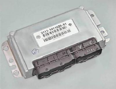
Electronic control unit (ECU)
Warning! Unqualified reprogramming of ROM or replacement of a chip from another car model (so-called chip tuning) may lead to engine malfunctions, failure of engine control system components, and engine damage.
The RAM stores fault codes detected by the ECU self-diagnostic system and operational information that the ECU microprocessor uses in calculations.
The EPROM stores the codes of the car's anti-theft system (immobilizer). This type of memory is non-volatile. After the immobilizer is activated, the ECU blocks the operation of the engine management system when trying to start the engine without special electronic keys.
The immobilizer control unit, fuses and relays for the engine management system are located under the instrument panel console.
The crankshaft position sensor (CPS) is designed to generate signals by which the ECU synchronizes its operation with the engine cycles. That is why this sensor is often called a synchronization sensor. The sensor operates on the principle of induction - when the crankshaft pulley teeth pass the sensor core, AC voltage pulses occur in the sensor circuit. The pulse frequency corresponds to the crankshaft rotation frequency. The teeth are located around the pulley circumference (6° apart). Two of them are spaced at an angular distance of 18°. This is done to generate reference signals in the sensor circuit - a kind of reference points relative to which the ECU determines the position of the crankshaft - the top dead centers in the first/fourth and second/third cylinders. The engine cannot operate with a faulty crankshaft position sensor. The crankshaft position sensor cannot be repaired - in case of a malfunction, it is replaced as an assembly.
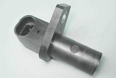
Crankshaft position sensor
Camshaft Position Sensor (CMP) is designed to generate a signal by which the ECU determines the top dead center (TDC) of the piston of the first cylinder during the compression stroke. Sometimes this sensor is called a phase sensor. The camshaft position sensor is installed in the plug of the cylinder head. The operating principle of the sensor is based on the Hall effect. When the protrusion of the ring fixed to the pulley of the camshaft of the intake valves passes through the slot in the end of the sensor, the sensor sends an electrical signal to the ECU. If the DPRV is faulty, the electronic control unit switches the system to the backup mode.
The camshaft position sensor is an electronic device that cannot be repaired. If the sensor is faulty, it must be replaced.
Knock sensor (DS) - piezoelectric, reacts to engine vibration. The knock sensor is installed on the front wall of the cylinder block. Based on the sensor signals, the ECU determines the moment of detonation during engine operation and adjusts the ignition timing accordingly. If the DD malfunctions, the electronic control unit switches the system to the backup mode.
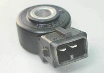
Knock sensor
Mass Air Flow Sensor (MAF) film type, installed between the air filter and the throttle valve. Based on the sensor signal, the ECU calculates the amount of air entering the engine cylinders. If the MAF is faulty, the electronic control unit switches the system to backup mode.
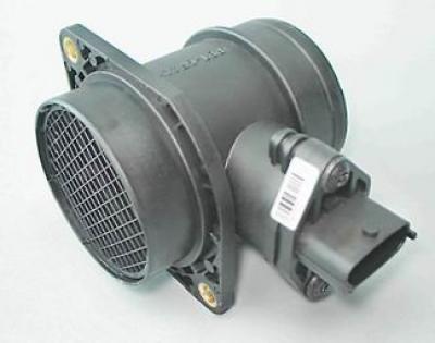
Mass Air Flow Sensor
Throttle Position Sensor (TPS) is installed on the throttle body and is connected to the throttle axis. The TPS is a variable resistor, the resistance of which depends on the angle of the throttle position. Based on the TPS signal, the electronic control unit determines the amount of throttle opening. If the TPS fails, the electronic control unit switches the system to backup mode.
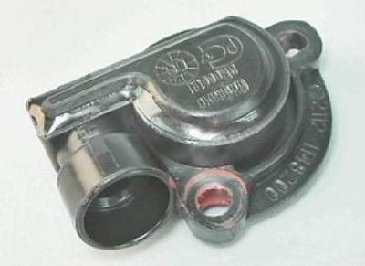
Throttle position sensor
Idle speed control (ISC) - is a shut-off valve driven by a stepper motor. The IAC is installed on the throttle body. The ECU, by sending a controlled signal to the IAC, regulates the engine crankshaft speed at idle, when starting and warming up the engine.
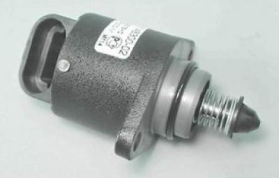
Idle speed control valve
Oxygen concentration sensor provides an output signal, which the ECU uses to determine the oxygen concentration in the exhaust gases. Based on the data received, the ECU adjusts the amount of fuel injected into the engine cylinders, thereby maintaining the optimal air-fuel mixture ratio (this is necessary for the efficient operation of the catalytic converter). The oxygen concentration sensor's sensitive element is located in the exhaust gas flow (before the catalytic converter). The sensor can only operate when its sensitive element is heated to a temperature of at least 300°C. To reduce the warm-up time, a heating element is built into the sensor. The sensor is installed in the lower part of the intake pipe.
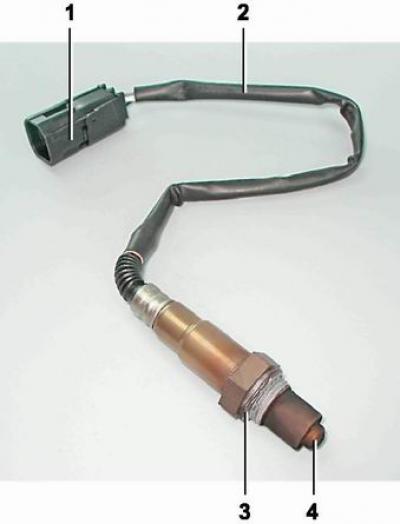
Oxygen concentration sensor: 1 - connection block; 2 - wiring harness; 3 - sealing ring; 4 - sensitive element with holes for supplying exhaust gases
Warning! The presence of lead and silicon compounds in the exhaust gases may cause the oxygen concentration sensor to fail. Therefore, the use of leaded gasoline is not allowed. When repairing the engine, do not use a sealant with a high silicone content (silicon compounds), vapors of which can enter the cylinders through the crankcase ventilation system and then into the exhaust tract. You should use a sealant that is specifically indicated on the packaging as being safe for the oxygen concentration sensor.
Coolant temperature sensor (CTS) - a semiconductor device - a thermistor, the electrical resistance of which changes with changes in the ambient temperature. The coolant temperature sensor is installed in the thermostat housing. The ECU evaluates the engine temperature mode based on the sensor resistance. The obtained data are used to calculate most control commands for the engine management system elements, as well as to turn on the electric fan of the engine cooling system. If the coolant temperature sensor fails, the electronic control unit switches the system to the backup mode.
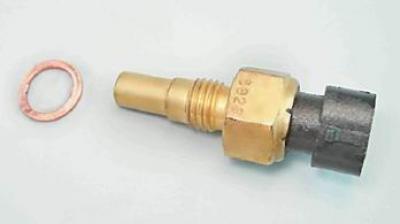
Coolant Temperature Sensor with Copper O-Ring
Vehicle speed sensor is installed on the gearbox. The sensor's operating principle is based on the Hall effect. Based on the pulses generated by the sensor, the ECU calculates the vehicle's speed. The signal from the sensor also goes to the speedometer.
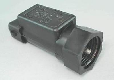
Vehicle speed sensor
The engine is equipped with an ignition coil, which consists of two two-terminal ignition coils, made in a single housing. Spark formation occurs in two cylinders simultaneously (1-4 and 2-3). The ignition coil is connected to the spark plugs by high-voltage wires with non-removable tips.
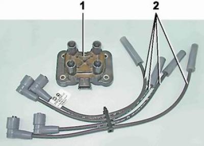
Elements of the ignition system of the engine 11183 (1.6i): 1 - ignition coil; 2 - set of high-voltage wires
Some 2111 (1.5i) engines on early production vehicles were equipped with an ignition module (instead of ignition coil). The module also consists of dual two-terminal coils installed in a common housing. Additionally, the housing contains an integrated circuit that controls the operation of the coils.
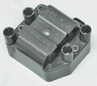
Ignition module
The engines use A17DVRM spark plugs, where:
- And the thread is M14x1.25;
- 17 heat rating;
- D length of threaded part 19 mm (with a flat landing surface);
- In the protrusion of the thermal cone of the insulator beyond the end of the threaded part of the housing;
- Ρ built-in resistor;
- m bimetallic central electrode.
The engine can be equipped with spark plugs of similar type from different manufacturers (see "Reference data").
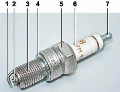
Spark plug: 1 - side electrode; 2 - central electrode (in the thermal cone of the insulator); 3 - threaded part of the body; 4 - sealing ring; 5 - hexagonal part of the body under the key; 6 - insulator (it has spark plug markings on it); 7 - contact tip (removable, threaded)
The injector is an electromagnetic needle valve, on the outlet pipe of which there is a sprayer with four calibrated holes. The injector opens on the signal of the ECU, and the fuel under pressure is injected directly onto the inlet valve. The amount of fuel entering the cylinder is regulated by the opening time of the injector. The engine has one injector per cylinder.
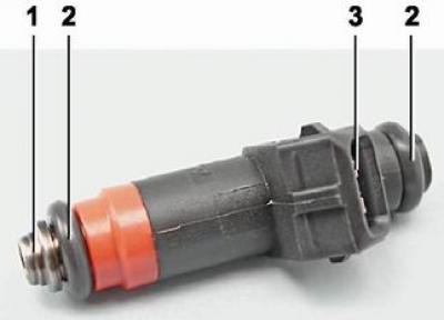
Engine injector 2111 (1.5i): 1 - sprayer; 2 - sealing rubber ring; 3 - terminals for connecting the wiring harness
The purge valve of the adsorber is installed on the cover of the adsorber housing.