




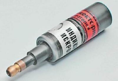
Tip: To quickly check the ignition system, you can use a spark indicator for fuel-injected engines. Put it on the spark plug and connect the high-voltage wire to it. When checking, follow the instructions included with the device.
Note: The 11183 (1.6i) engine uses an ignition coil. The 2111 (1.5i) engine may use an ignition coil or ignition module (see "Description of the system"). The ignition coil replacement is shown below. The module replacement is performed in a similar manner.
To complete the work you will need a multimeter (in voltmeter and ohmmeter mode).
Sequence of execution
1. Prepare the car for work (see "Preparing the car for maintenance and repair"), turn off the ignition.
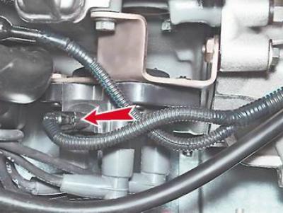
2. Having released the retainer, we disconnect the wiring harness block from the terminals of the ignition coil (module).
3. Turning on the ignition, we measure the voltage between pin 15 and the "ground" with a voltmeter (for ignition coil) or terminals C and D (for ignition module) wiring harness pads.
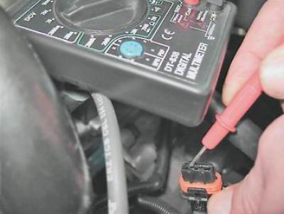
Recommendation: The voltage should be at least 12 V. If the voltage does not reach the socket or is less than 12 V, the battery is discharged, the power supply circuit is faulty, or the ECU is faulty. You can verify that the ignition module is faulty by replacing it with a known good one. The ignition coil can be checked with an ohmmeter.
Warning! After taking measurements, turn off the ignition.
4. Disconnect the high-voltage wires from the spark plugs (see "High voltage wires - checking and replacement").
5. With a socket wrench by 13 mm unscrew the two bolts of the upper mounting of the ignition coil bracket.
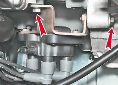
6. Key by 17 mm having loosened the lower bolt of the ignition coil bracket, we remove the bracket together with the coil.
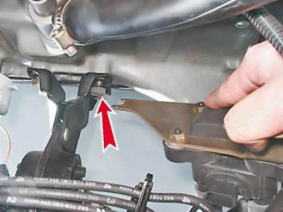
7. Disconnect the high-voltage wires from the ignition coil (module) (see "High voltage wires - checking and replacement").
8. Using an ohmmeter, measure the electrical resistance between the central terminal 15 and the body (bracket). The device should show the absence of a short circuit of the primary winding of the coil to the "ground". We measure the electrical resistance between the central terminal 15 and the outer terminals - 1a and 1b. The resistance of each of the primary windings of the coil should be about 0.5 Ohm.
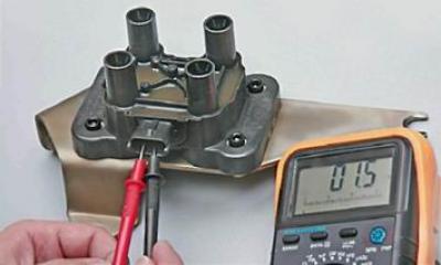
Note: When measuring small values of electrical resistance (about 1 Ohm) it is necessary to take into account the internal resistance of the device, which can be determined by short-circuiting the ohmmeter probes.
9. Using an ohmmeter, measure the resistance between the high-voltage terminals of coil 1 and 4, and then 2 and 3. The resistance of the windings should be about 5.4 kOhm.
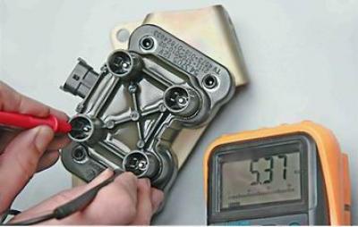
Recommendation: A faulty ignition coil must be replaced.
10. With a hex key by 5 mm we unscrew the four screws that secure the coil to the bracket and remove the coil.
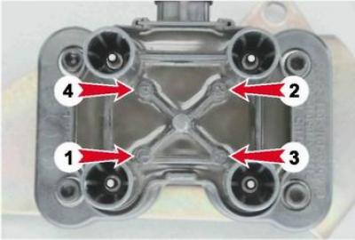
11. Install the ignition coil in the reverse order of removal. Connect the high-voltage wires in accordance with the cylinder numbers printed on each wire and on the coil body next to the terminals.
[Original source is on the resource: vazbook.ru]
Tip: Since the terminal numbers on the coil installed on the engine are not visible, it is better to connect the high-voltage wires to the terminals of the ignition coil before installing it on the engine.