
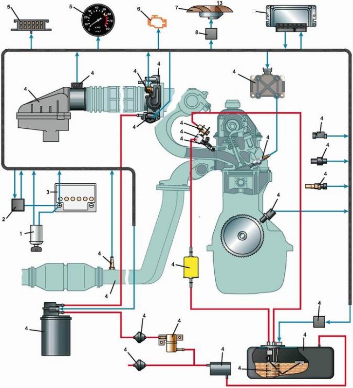
Elements of the engine management system: 1 - diagnostic connector; 2 - tachometer (if installed); 3 - control lamp for a malfunction of the engine management system; 4 - throttle position sensor; 5 - throttle body; 6 - radiator electric fan; 7 - electric fan relay; 8 - electronic control unit; 9 - coil (module) ignition; 10 - vehicle speed sensor; 11 - spark plug; 12 - coolant temperature sensor; 13 - crankshaft position sensor; 14 - relay of the electric fuel pump; 15 - fuel tank; 16 - electric fuel pump; 17 - bypass valve; 18 - safety valve; 19 - gravity valve; 20 - fuel filter; 21 - check valve; 22 - adsorber purge valve; 23 - receiving pipe; 24 - oxygen concentration sensor; 25 - battery; 26 - switch (lock) ignition; 27 - main relay; 28 - nozzle; 29 - fuel pressure regulator; 30 - idle speed controller; 31 - air filter housing; 32 - mass air flow sensor
Engine management system with distributed fuel injection - electronic. It controls the amount of air and fuel entering the engine cylinders, turns on and off the fuel pump, controls sparking on the spark plugs and corrects the ignition timing, regulates the idle speed of the crankshaft, and controls the electric fan of the engine cooling system.
The system consists of the following elements:
- electronic control unit (ECU);
- sensors:
- crankshaft position;
- throttle position;
- oxygen concentration;
- coolant temperature;
- mass air flow;
- vehicle speed;
- executive devices:
- main relay;
- fuel pump relay;
- ignition coil;
- cooling fan relay;
- tachometer (for vehicles with instrument panel model 2107);
- a control lamp for a malfunction of the engine management system;
- idle speed controller;
- adsorber purge valve;
- nozzles;
- connecting wires;
- diagnostic sockets.
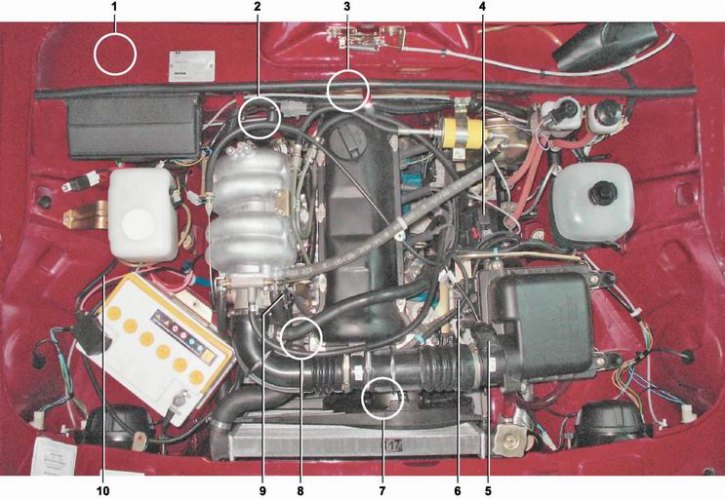
Location of elements of the engine management system: 1 - electronic control unit, relays and fuses (located under the glove box in the cabin); 2 - oxygen concentration sensor (located on the intake pipe); 3 - vehicle speed sensor (located on the gearbox); 4 - adsorber purge valve; 5 - mass air flow sensor; 6 - ignition coil; 7 - crankshaft position sensor (located on the camshaft drive cover); 8 - coolant temperature sensor (located in the cooling system); 9 - throttle position sensor; 10 - wiring harness control system
The control lamp for a malfunction of the engine management system is located on the instrument panel in the signaling unit (see "Controls and control devices"). When the ignition is turned on, the system is tested for serviceability, while the lamp lights up and goes out after starting the engine. Turning on the lamp when the engine is running signals the need to check the engine management system. On some modifications of cars the control lamp can be located on the top insert of the radio receiver panel.
The main control element of the system is electronic control unit (ECU, or as it is often called - controller), with built-in microprocessor.
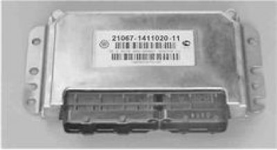
Electronic control unit (ECU)
In fact, an ECU is a specialized minicomputer in which only one program is installed - engine control, and sensors and actuators are the peripheral equipment of this computer. The unit receives and analyzes the sensor signals. Based on the received data, the block calculates control commands and issues them to the actuators. There are two types of memory in the unit: ROM (ROM) and working memory (RAM).
ROM - non-volatile memory (that is, the information in the memory is retained when the power is turned off). The ROM stores the calculation program and the data necessary for the calculation (engine parameters, transmission ratios and other characteristics). During operation, the ECU monitors the health of all elements and circuits of the engine management system. Having detected a malfunction, the ECU puts the engine management system into standby mode and turns on the engine malfunction indicator lamp. The engine will then be able to continue running (except in the case of a malfunction of the crankshaft position sensor, see below), which allows you to get to the place of repair on your own. The ECU writes the codes of the detected faults to the RAM (RAM). It also stores operational information that the ECU microprocessor uses in calculations. When the battery is disconnected from the car's on-board network, all information stored in RAM will be lost.
The electronic control unit is installed in the passenger compartment under the glove box on a bracket attached to the partition of the engine compartment.
The car has an engine management system based on EBUM7.9.7 (21067-1411020-11/2104-1411020-10) complying with EBPO II toxicity standards.
Note. 3BYM15.4N and January-5.13 are installed on some of the produced cars (see "Electrical circuits").
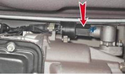
crankshaft position sensor (DPKV) is designed to generate signals by which the ECU synchronizes its work with the cycles of the engine's working process. Therefore, often this sensor is called a synchronization sensor. The sensor is installed in the hole of the camshaft drive cover bracket.
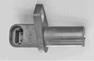
crankshaft position sensor
Location of crankshaft position sensor
The operation of the sensor is based on the principle of induction - when the teeth of the crankshaft pulley pass by the sensor core, alternating current voltage pulses occur in the sensor circuit. The frequency of appearance of pulses corresponds to the frequency of rotation of the crankshaft. The teeth are located around the circumference of the pulley at the same distance. The distance between the two of them is made larger. This was done to form reference signals in the sensor circuit - a kind of reference points, relative to which the ECU determines the position of the crankshaft. Engine operation with a faulty crankshaft position sensor is not possible.
Mass air flow sensor (DMRV) film type mounted on the air filter housing.
Based on the signal from the sensor, the ECU calculates the amount of air entering the engine intake manifold. In the event of a malfunction of the DMRV, the electronic control unit switches the system to a standby mode of operation.
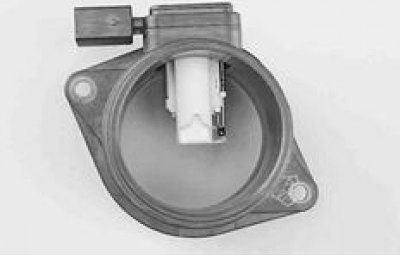
Mass air flow sensor
Throttle position sensor (TPS) is a variable resistor, the resistance of which depends on the angle of rotation of the throttle.
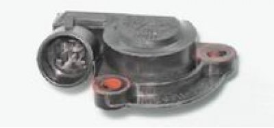
Throttle position sensor
The sensor is mounted on the throttle body and connected to its axis. Based on the TPS signal, the electronic control unit determines the value of the throttle valve opening angle. In the event of a malfunction of the TPS, the electronic control unit switches the system to a backup mode of operation.
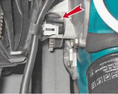
Oxygen concentration sensor determines the oxygen content in the exhaust gases and transmits a signal to the computer.
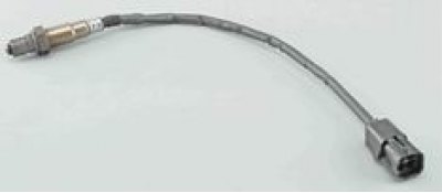
Oxygen concentration sensor
It is installed in the exhaust pipe of the exhaust system.
Location of the oxygen concentration sensor
Based on the data received from the oxygen concentration sensor, the ECU adjusts the amount of fuel injected into the intake manifold by the injectors, thereby maintaining the optimal proportion of the air-fuel mixture necessary for the efficient operation of the catalytic converter. The sensor starts working when its sensitive element warms up to a temperature of at least 360°C. To reduce the warm-up time, a heating element is built into the sensor.
Attention! The presence of lead and silicon compounds in the exhaust gases can disable the oxygen concentration sensor. Therefore, leaded gasoline should not be used (it contains lead compounds). When repairing the engine, it is also impossible to use a sealant with a high content of silicone (silicon compounds), whose vapors can enter the cylinders through the crankcase ventilation system and then into the exhaust system. A sealant should be used where the manufacturer states on the packaging that the sealant is safe for the oxygen sensor.
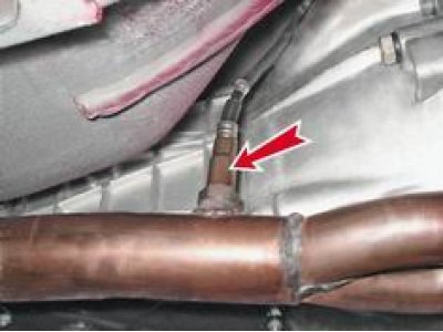
coolant temperature sensor (DTOZH) - a semiconductor device - a thermistor, the electrical resistance of which varies depending on the temperature of the coolant.
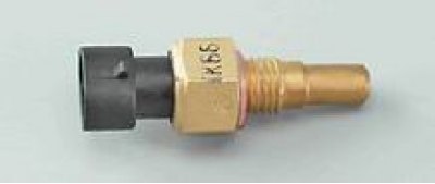
coolant temperature sensor
DTOZH is installed in the threaded hole of the pipe of the engine cooling system.
Location of coolant temperature sensor
By the value of the resistance of the sensor, the ECU evaluates the temperature regime of the engine. The data obtained is used in the calculation of most of the control commands of the engine management system, as well as to turn on the electric fan of the engine cooling system.
In the event of a malfunction of the DTOZH, the electronic control unit switches the system to a backup mode of operation.
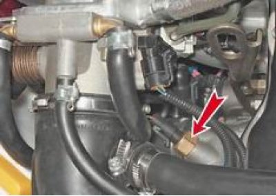
Operating principle vehicle speed sensor based on the Hall effect.
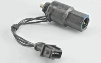
Vehicle speed sensor
The sensor is attached to the speedometer drive housing, which is mounted on the gearbox. The speedometer drive cable is attached to the sensor.
Vehicle speed sensor location
Based on the pulses generated by the sensor, the ECU calculates the speed of the car.
Diagnostic connector block designed to connect an external diagnostic device (type DST-2M) to the engine management system. Block A is installed on the same bracket with the fuse and relay box B on the front panel under the glove box.
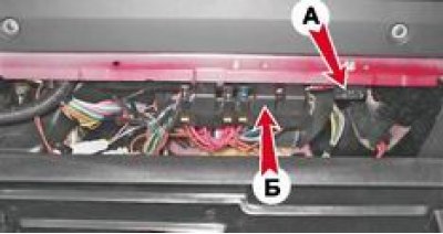
Location of the relay and fuse diagnostic socket
The engine management system circuits are protected by 7.5A and 15A flag type fuses.
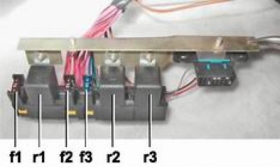
Fuses and relays for the engine management system: fl - main relay circuit fuse (7,5 A); f2 - ECU fuse (7,5 A); f3 - fuel pump circuit fuse (15 A); rl - main relay; r2 - fuel pump relay; r3 - electric fan relay.
Note. On vehicles with Ml5.4N and January-5.13 ECUs, f7 and f2 fuses with a rating of 75A are installed.
Ignition coil mounted on the left side of the cylinder block on the bracket. The coil is two high-voltage transformers combined into one non-separable unit. The outputs of the secondary winding of one coil are connected by high-voltage wires to the candles of the 1st and 4th cylinders, the other - to the candles of the 2nd and 3rd cylinders. The numbers of the cylinders, with the candles of which the coil leads are connected, are marked next to the leads.
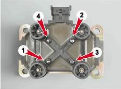
Ignition coil
High-voltage electrical impulses from the coil are applied simultaneously to the spark plugs of two cylinders: one at the end of the compression stroke, where the working mixture ignites, and the other at the end of the exhaust stroke (the candle fires).
On vehicles with ECU M1.5.4N and January-5.1.3, an ignition module is installed instead of a coil. It combines two ignition coils and two electronic units that control the coils.