




- multimeter (in voltmeter and ohmmeter mode);
- pieces of wire.
Examination
1. Prepare the car for work (see "Preparing the car for maintenance and repair").
2. Release the wiring harness connector retainer and disconnect the connector from the idle speed control valve.
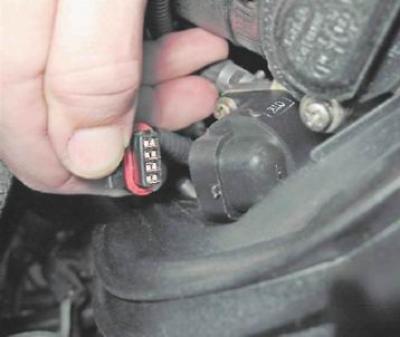
3. Connect the negative probe of the voltmeter to the engine ground.
4. Turn on the ignition and use a voltmeter to measure the voltage at terminals A and D of the wiring harness connector (terminal designations are printed on the socket).
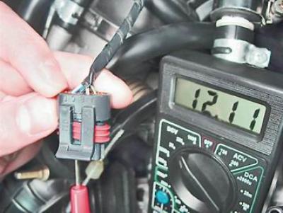
Note: The voltage must be at least 12 V. If the voltage does not reach the connector or is less than 12 V, the battery is discharged, the power supply circuit is faulty, or the ECU is faulty.
Warning! After completing the voltage measurement, turn off the ignition.
Removal
Note: On engine 11183 (1.6i), unscrew the two nuts securing the throttle assembly to the receiver. Move the throttle assembly away from the end of the receiver by 10-15 mm (without removing from the studs) so that access to both idle speed control mounting screws is open.
1. Using a Phillips screwdriver, unscrew the two screws securing the idle speed control to the throttle body.
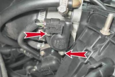
2. Remove the idle speed control valve.
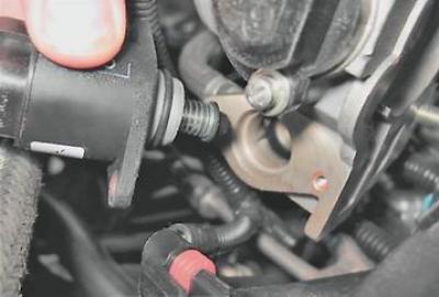
3. Using an ohmmeter, measure the resistance between the terminals of the windings.

Note: The electrical resistance between terminals A-B and CD should be about 53 ohms. The resistance between terminals A-C and BD should be greater (strive for infinity). A faulty regulator must be replaced.
Installation
Warning: Before installing a new regulator, make sure that the valve needle protrudes no more than 23 mm.
1. Using a depth gauge, measure the protrusion of the needle of the new valve.
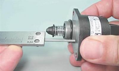
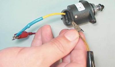
2. If the valve protrusion is more than 23 mm, then we recess the valve into the body as follows:
a) Using a wire, connect the positive terminal of the battery to terminal D of the regulator (the connection of the wire to the terminal must be insulated).
b) With the bare end of the wire connected to the negative terminal of the battery, briefly touch the terminal C of the harness block. Since the valve moves very slowly, we touch it repeatedly, reproducing the operation of a pulse power supply.
3. We check the condition of the sealing ring by visual inspection. We replace the damaged ring.
4. Install the regulator in the reverse order of removal.