
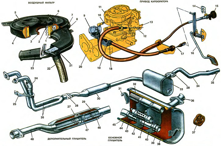
1. Filter element. 2. An arm of fastening of a cover of the air filter. 3. Seal. 4. Air filter housing. 5. Cover. 6. Branch pipe of the upper exhaust hose of ventilation of the crankcase. 7. Spring latch. 8. Arrow for the correct installation of the filter cover. 9. Intermediate lever. 10. Throttle actuator rod. 11. Carburetor. 12. Thrust drive air damper. 13. Choke control lever. 14. Sling bracket. 15. Air damper drive handle. 16. Throttle pedal lever. 17. Drive cable. 18. Adjusting nuts. 19. An arm of the intermediate lever. 20. Inlet pipe. 21. Seasonal damper. 22. Corrugated hose. 23. Receiving pipe. 24. Heated air intake. 25. Cylinder block bracket. 28. Receiving pipes. 27. Partition of the additional muffler. 28. Pipe connections. 29. The body of the additional muffler. 30. Additional muffler. 31. Suspension bracket for the main muffler. 32. Intermediate perforated pipe. 33. Main muffler. 34. Exhaust pipe. 35. Exhaust pipe suspension bracket. 36. Rear pipe of the main muffler. 37. Pillow pendants. 38. Housing of the main muffler. 39. Plug. 40. Rear partition. 41. Medium perforated pipe. 42. Front partition. 43. Inlet perforated pipe. 44. Thermal insulation. 45. Silencer cover. 46. Perforated pipe additional muffler. 47. Diaphragm. 48. Front pipe additional muffler.
Air filter
The air filter cleans the air entering the carburetor from mechanical impurities. The engine is equipped with a single-stage dry-type air filter, with a replaceable filter element, with manual seasonal adjustment of air heating.
The air filter consists of a body 4, a cover 5, a filter element 1, an inlet pipe 23, a seasonal adjustment damper 21 with a lever and a fixing spring, and a corrugated hose 22 connected to the heated air intake 24.
The air filter housing 4 is stamped from a steel sheet. The body is mounted on the carburetor and sealed with a rubber seal 3. The body is fastened with nuts on the studs of the cylinder head cover and the carburetor bracket. A suction pipe 23 is welded to the filter housing, in which a seasonal adjustment damper 21 is installed. It is equipped with a branch pipe from below, connected by a corrugated hose 22 with an air intake 24 of heated air. The air intake is welded to the intake pipe 26. The damper 21 is fixed by a spring and has two positions: «COLD» (cold) when driving a car in summer and «NOT» (warm) when operating in winter. Tags «COLD» and «NOT» printed on the intake manifold.
The cover 5 of the filter is attached to the body 4 with four spring latches 7 and additionally with a nut to the bracket 2 welded to the filter body. The tightness of the housings with the cover is ensured by a polyurethane foam gasket glued to the filter cover. From above, the cover has a branch pipe b of the upper exhaust hose for crankcase gases. To reduce intake noise, the filter cover 5 is installed in such a way that the arrows stamped on the cover and inlet pipe 23 are directed towards each other. The cover and filter housing are painted with black enamel.
Dry filter element 1 is used from other air filters of VAZ vehicles. The filter part of the element has the form of an accordion made of special filter cardboard, is installed in perforated outer and inner shells made of tin and is poured into elastic covers from the ends, due to which, when the air filter cover is installed, the filter element is reliably sealed with the filter housing and cover. To increase the dust capacity of the filter element, a pre-cleaner made of synthetic wool is put on the outer perforated shell.
When the engine is running, air enters the air filter housing through the intake pipe 23 from the engine compartment or through the heated air intake 24 from the zone of the exhaust pipes 26 through the corrugated hose 22.
The filter element must be replaced periodically every 15,000 km by a new one. For continuous operation in areas with high dust content, the filter element must be changed every 10,000 km. Cleaning or reconditioning of the filter element is not recommended as the filter paper may be damaged.
Carburetor control drive
The drive for controlling the throttle and air dampers of the carburetor is cable. Throttle valves are controlled by pressing the pedal in the car. The pedal is welded to the lower and upper levers and the axle, which rotates in two plastic bushings on the body front bracket and secured with a locking bracket. A polyvinyl chloride pad from a VAZ-2108 car is put on the pedal. A stop gasket is installed on the pedal bracket, which limits the extreme initial position of the pedal (in the figure, the stop with the gasket is not shown).
The upper pedal lever is connected by a drive cable 17 to an intermediate lever 9 mounted on the axis of the bracket 19 of the intermediate lever. The bracket is fastened with nuts on two studs of the inlet pipe 20. The rear tip of the cable 17 has a rubber damper that absorbs vibrations from the power unit to the pedal. The cable is placed in a sheath, the front end of which is fastened with adjusting nuts 18 on the bracket 19 of the intermediate lever. The front end of the cable is connected to the intermediate lever 9, which is connected by a ball head to the rod 10 and the carburetor throttle actuator lever. Rod 10 is interchangeable with the rod of a VAZ 2104 car (tie rods from the car VAZ-2101).
The throttle actuator pedal in the initial position is pressed against the stop, and the throttle valves are in the closed position with the help of return springs mounted on the pedal axis and on the intermediate lever bracket.
With the throttle valves of the carburetor fully closed, cable 17 must be taut. The tension is provided by adjusting nuts 18. The deflection of the cable 17 above the bracket 19 towards the carburetor before turning the intermediate lever 9 should be no more than 5 mm. The length of the rod 10 along the ball sockets should be adjusted by screwing on the tips and be 74...79 mm. The total pedal travel must not exceed 64.7 mm. With a longer pedal stroke, bend the pedal bracket stop and once again check the fullness of the throttle valves and the tension of the drive cable.
The air damper of the carburetor is controlled by the handle 15 of the air damper actuator, located in the passenger compartment under the instrument panel. The handle is connected by a rod 12 to the levers 13 for controlling the air damper. The end of the shell rod 12 is fixed on the carburetor bracket.
When the handle is pulled out, the air damper closes, when the handle is pushed in, it opens.
When adjusting the air damper drive, it is necessary to fix the end of the rod 12 on the lever 13 so that when the handle 15 is extended, the air damper is completely closed, and when the handle is recessed, it is completely open.
Exhaust gas outlet
Exhaust gases are released through three non-separable units: exhaust pipes 26, additional 30 and main silencers 33, complete with pipes and exhaust pipe 34. All units are connected to each other by means of flanges installed at the ends of the flared pipes. In spare parts, the units are supplied complete with flanges. O-rings with a spherical surface are installed between the flared ends of the pipes. The flanges are tightened with bolts, providing a rigid connection of the exhaust pipe 34. Springs are installed under the bolts for connecting the exhaust pipes 26 and the additional muffler, allowing some displacement of the exhaust pipes during the vibration of the power unit due to the spherical surface of the sealing ring.
Receiving pipes
Down pipes 26 consist of two front down pipes with flanges and a back down pipe, which are made in one unit. Receiving pipes 26 are made of stainless steel having increased corrosion resistance.
The exhaust pipes are attached to the cylinder head studs with disposable self-locking nuts. To increase rigidity, the exhaust pipes are additionally mounted on the bracket 25 of the engine block. Ferronite gaskets are installed between the exhaust pipe flanges and the cylinder head. An air intake 24 of heated air is welded to the left exhaust pipe.
Silencers
Additional 30 and main 33 mufflers consist of housings, inlet and outlet pipes, perforated pipes and baffles. All muffler parts are made of 08kp steel clad with a layer of aluminum on both sides.
The cases and covers of the mufflers are interconnected by rolling. The main muffler has two partitions: rear 40 and front 42, forming three noise suppression chambers of a certain range of medium-high frequencies. Additional muffler 30 has one baffle 27 and diaphragm 47 and serves to suppress high frequency noise.
Asbestos sheet or other insulating material is placed between the housing 38 and the protective casing 45 for thermal insulation and noise reduction at the main muffler.
The main muffler 33 and the exhaust pipe 34 are fixed to the body brackets with four rubber pads 37 suspensions.
Downpipes, mufflers and exhaust pipe are painted on the outside with aluminum heat-resistant enamel KO-828.