
Camshaft
Cast, cast iron, the same for all engine models. Relies on 5 necks and rotates in an aluminum bearing housing mounted on the cylinder head. A driven sprocket is attached to the front end of the camshaft (pulley on cars 2105). From axial movements, the camshaft is held by a thrust flange placed in the groove of the front bearing journal of the shaft.
On VAZ vehicles until April 1982, camshafts with cams and bearing journals hardened by high-frequency currents were installed. From April 1982, nitrided camshafts were installed. Since 1984, the year of manufacture has been marked on the shafts. Since 1985, camshafts with cam cams have been installed; these shafts have a distinctive hex collar between the 3rd and 4th jaws.
Camshaft drive
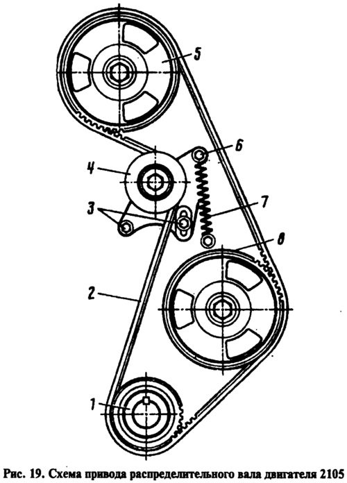
On engines 2105, a camshaft belt drive is used. A toothed drive pulley 1 is mounted on the crankshaft (pic. 19), from which, with the help of a toothed belt 2, two driven pulleys are driven: the camshaft pulley 5 and the auxiliary drive shaft pulley 8. The belt tension is adjusted using the tension roller 4, which is mounted on the bracket 6 and rotates on a double-row ball bearing. The belt tension is set by the spring 7 after the bolts 3 are loosened. The drive is isolated from oil ingress by three seals covering the pulley hubs. Outside, the drive is closed with three plastic covers: top, middle and bottom (see fig. 60).
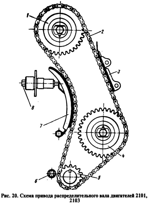
On engines 2101 and 2103, the camshaft is driven by a two-row roller chain 2 (pic. 20) from the drive sprocket 5 of the crankshaft. The same chain drives the sprocket 4 of the auxiliary drive shaft. The chain drive has a semi-automatic tensioner 8 with a shoe 7 and a chain damper 3 with rubber pads. A restrictive pin 6 is installed at the bottom of the cylinder block, which prevents the chain from falling into the crankcase when the camshaft sprocket 1 is removed from the car.
For correct alignment of pulleys (stars), i.e. for setting the valve timing there are upper and lower installation marks. Upper located on the pulley (asterisk) camshaft and bearing housing (see fig. eleven), lower marks - on the pulley (asterisk) crankshaft and camshaft drive cover (see fig. 24). When the drive is covered (engine mounted on car), then you can use the pulley marks to set the ignition timing (see fig. 73). In this case, mark 4 on the alternator drive pulley against the long mark 3 on the camshaft drive cover.
The camshaft drives of engines 2103 and 2103 differ in three parts: chain 2 (see fig. 20), shoe 7 of the tensioner and damper 3 of the chain.
The 2101 engine chain has 114 links, i.e. it has an odd number (57) internal and external links. The 2103 engine chain has 116 links, i.e. an even number (58) internal and external links. It is easy to check whether the number of outer links is even or odd by adding together both branches of the chain.
To distinguish the shoes of the chain tensioners, there is a mark in the form of a cylindrical recess on the end surface of the bracket welded to the shoe. For 2101 motor boots, the mark is located at the top of the bracket, and for 2103 motor boots, it is at the bottom.
To distinguish the damper of the engine 2103, there is a vertical protruding risk with a length of 25 mm on the surface of the rubber lining.