
English Русский
Български
Беларускі
Український
Српски
Hrvatski
Română
Polski
Slovenský
Magyar
| Articles | Contacts | Sitemap |   
Repair and maintenance Lada Repair and maintenance Mazda Repair and maintenance Mitsubishi Repair and maintenance Toyota Repair and maintenance Land Rover Repair and maintenance Hyundai Repair and maintenance Nissan
VAZbook.ru


Main     1111   2101   2105   2106   2107   2109   2110   2115   2121  
VAZ-2114 (2004-2013) VAZ-2115 (1997-2012)
  • Main
  • «Samara-2»
  • VAZ-2114
  • Transmission
  • Car gearbox
  • Gear shift drive — removal, installation and adjustment

Gear shift drive — removal, installation and adjustment (VAZ-2114)

            0

Contents: Removal ↓ Installation ↓ Adjustment ↓
To complete the work you will need an assistant, as well as:
  • inspection pit or overpass;
  • roulette.

Removal


1. Prepare the car for work (see "Preparing the car for maintenance and repair").

2. Pry off the cover with a screwdriver...
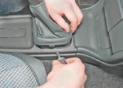
2. Pry off the cover with a screwdriver...


...and, turning the handle to the right and left, we pull it up together with the cover, and also remove the polyethylene tube and foam ring from the lever.
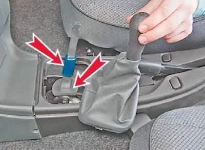
...and, turning the handle to the right and left, we pull it up together with the cover, and also…


3. Holding the key by 13 mm the bolt that secures the rod to the lever from turning, use a second wrench of the same size to unscrew the nut.

(The original source is located on the website vazbook)
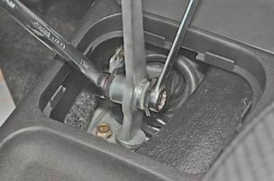
3. Holding the key by 13 mm the bolt that secures the rod to the lever from turning, use a second…


4. Remove the bolt and take the lever out of the traction fork.


5. Remove the plastic centering bushings.
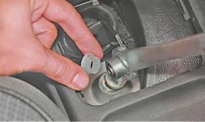
5. Remove the plastic centering bushings.


6. Remove the steel spacer sleeve from the lever hole.
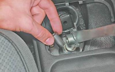
6. Remove the steel spacer sleeve from the lever hole.


7. For ease of removal of the draft, remove the floor tunnel lining (see "Floor Tunnel Overlay - Removal and Installation").

8. From below the car with a key by 10 mm we unscrew the four fastening nuts and remove the screen.
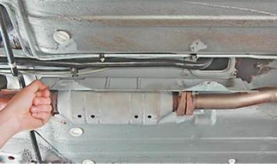
8. From below the car with a key by 10 mm we unscrew the four fastening nuts and remove the screen.


9. Mark the relative position of the drive rod and the hinge.
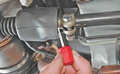

9. Mark the relative position of the drive rod and the hinge.


10. Holding the key by 13 mm clamp tightening bolt, using a second wrench of the same size, loosen the nut.
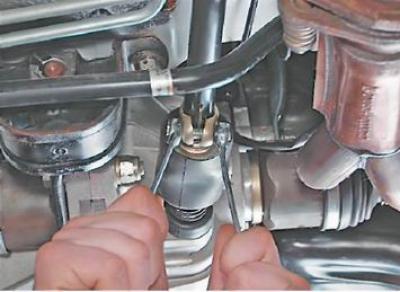
10. Holding the key by 13 mm clamp tightening bolt, using a second wrench of the same size, loosen…


11. Use a screwdriver to loosen the clamp and move it along the rod.
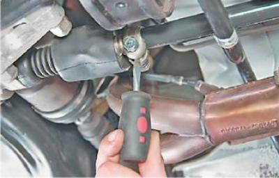
11. Use a screwdriver to loosen the clamp and move it along the rod.


12. Apply penetrating lubricant to the connection between the rod and the hinge.
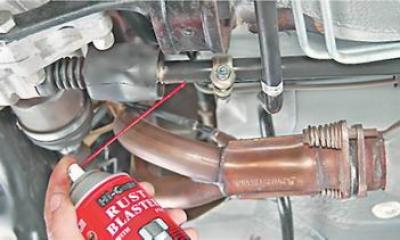
12. Apply penetrating lubricant to the connection between the rod and the hinge.


13. Use a screwdriver to loosen the rod.
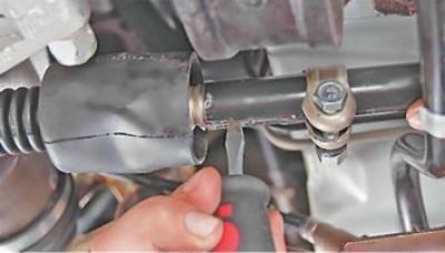
13. Use a screwdriver to loosen the rod.


14. Disconnect the rod from the hinge.
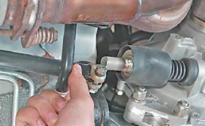
14. Disconnect the rod from the hinge.


15. In the car interior, remove the rubber seal from the hole in the car body.
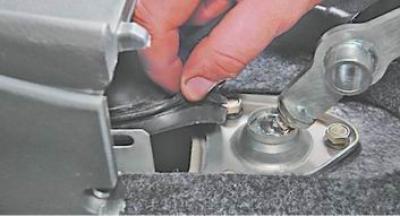
15. In the car interior, remove the rubber seal from the hole in the car body.


16. Push the seal and rod down through the hole.
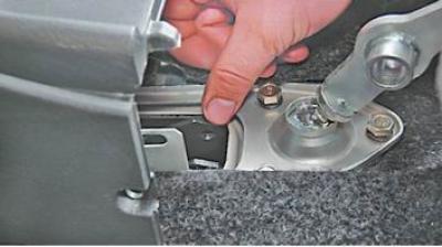
16. Push the seal and rod down through the hole.


17. Remove the rod assembly with the seal from the inspection pit.
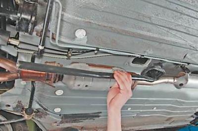
17. Remove the rod assembly with the seal from the inspection pit.


18. Remove the seal from the rod.
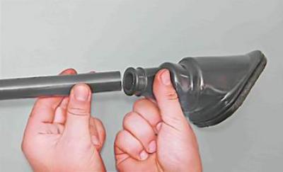
18. Remove the seal from the rod.


19. To remove the lever, remove the right instrument panel console trim (see "Instrument panel - removal and installation").

20. Key by 13 mm we unscrew the two bolts of the rear mounting bracket of the lever...
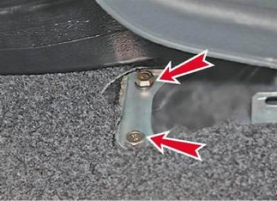
20. Key by 13 mm we unscrew the two bolts of the rear mounting bracket of the lever...


...and three front ones.
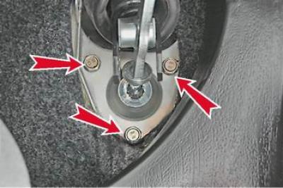
...and three front ones.


21. Remove the bracket together with the lever.
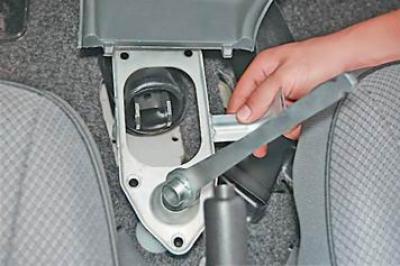
21. Remove the bracket together with the lever.


Installation


We install the parts of the gear selection mechanism drive in the reverse order. At the same time, we apply plastic grease to the threaded part of the rod mounting bolts and align the marks made before disassembly.

We check the operation of the gear shift mechanism and, if necessary, adjust its drive (see below).

Adjustment


1. Move the gear shift lever to neutral position.

2. Loosen the clamp of the gear shift mechanism drive rod (see above, p. 10).

3. In the car, the assistant sets the lever almost vertically (shifting back a little), and holds it in this position.

4. Key by 13 mm tighten the nut of the drive rod mounting clamp clamp bolt, holding the bolt from turning with a wrench of the same size.

5. Check whether all gears are easily engaged. If necessary, repeat the adjustment.

Note: When engaging third or fifth gear, your hand should not rest against the instrument panel console. When engaging reverse or fifth gear, the gearshift lever should not fall onto the front seat cushions (set to the middle position).


This article is available at russian, bulgarian, belarusian, ukrainian, serbian, croatian, romanian, polish, slovak, hungarian
The text was reviewed by the specialist: Grigory Vologodtsev

Share with friends:

Previous articles
VAZ-2114: Car gearbox
Next articles

Gearbox — Oil change
Gearbox — Checking the oil level
Gearbox — technical condition check
Description of the gearbox design
Gearbox specifications
Front Wheel Drive Seals — Replacement
Primary shaft seal — replacement
Gearbox — removal and installation

More articles from other manuals on VAZ cars:
➠ Gear shift drive — removal, installation and adjustment VAZ-2110 (1995-2007)
➠ Gear shift drive VAZ-1111 (1988-1996)
➠ Checking the front wheel drive and gear shift linkage VAZ-21099 (1990-2004)
➠ Gear shift mechanism VAZ-2101 (1970-1983)
➠ Oil pump drive shaft and gear VAZ-21051 (1979-2010)
Link in different formats to this page


Visitor comments

No comments yet


How much will 23 + 48 ?


VAZ-2114 (2004-2013) 
  • General information
  • Operation and maintenance
  • Power unit
  • Engine repair
  • Cooling system
  • Supply system
  • Control system
  • Exhaust system
  • Transmission
  • Clutch
  • Car gearbox
  • Front wheel drives
  • Chassis
  • Wheels and tires
  • Front suspension
  • Rear suspension
  • Steering
  • Brake system
  • Body
  • Exterior
  • Interior
  • Doors and glass
  • Tailgate
  • Ventilation and heating
  • Electrical equipment
  • Equipment and devices
  • Headlights and lighting
  • Engine electrics
  • Electrical circuits


VAZ-2115 (1997-2012) 
  • General information
  • Vehicle device
  • Operation manual
  • Vehicle malfunctions
  • Car care
  • Power unit
  • Engine repair
  • Cooling system
  • Supply system
  • Control system
  • Exhaust system
  • Transmission
  • Clutch
  • Car gearbox
  • Front wheel drives
  • Chassis
  • Front suspension
  • Rear suspension
  • Steering
  • Brake system
  • Body
  • Exterior
  • Interior
  • Doors, covers and windows
  • Electrical equipment
  • Equipment and devices
  • Headlights and lighting
  • Engine electrics
  • Anti-theft system


VAZbook.ru © 2017 · Mobile version · Contact with administration · Sitemap: EN BG BY UA RS HR RO PL SK HU · Site search · News and articles VAZ-1111 · VAZ-11113 · VAZ-2101 · VAZ-21011 · VAZ-2104 · VAZ-2105 · VAZ-21051 · VAZ-2106 · VAZ-21061 · VAZ-2107 · VAZ-21099 · VAZ-2109 · VAZ-2108 · VAZ-2110 · VAZ-2112 · VAZ-2114 · VAZ-2115 · VAZ-2121 · VAZ-21213 · VAZ-21214 ·
The site stores technical data using cookies to improve the service.