
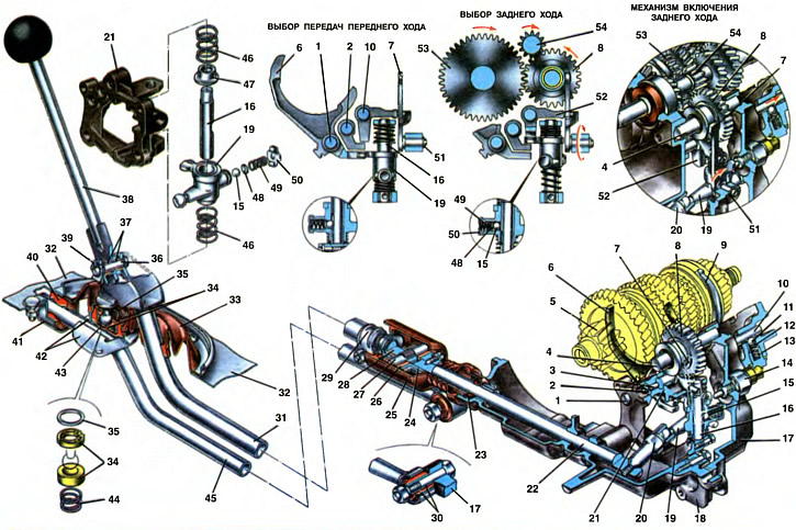
1. The rod of the shift fork of I and II gears. 2. Stem of the shift fork of III and IV gears. 3. Locking cracker of the locking device. 4. Axis of an intermediate gear wheel of a backing. 5. Secondary shaft. 6. Fork shifting I and II gears. 7. Reverse fork. 8. Intermediate reverse gear. 9. Switching fork III and IV gears. 10. Reverse fork rod. 11. Stem retainer ball. 12. Retainer sleeve. 13. Detent spring. 14. Reversing light switch. 15. Gear selector lock. 16. The axis of the gear selector lever. 17. Transmission housing. 18. Clutch housing. 19. Two-arm gear selection lever. 20. The lever of a rod of a choice of transfers. 21. Housing gear selection mechanism. 22. Gear selection rod. 23. Stem seal. 24. Hinge body. 25. Protective cover of the hinge. 26. hinge bushing. 27. Hinge axis. 28. Hinge tip. 29. A coupling collar of draft of a drive of a gear change. 30. Rubber-metal joint jet thrust. 31. Gearshift drive rod. 32. Body floor. 33. Protective cover. 34. Ball joint. 35. Support washer. 36. Finger. 37. Bushings. 38. Gear lever. 39. Locking bracket. 40. Support bush jet thrust. 41. Jet thrust support. 42. Gear lever housing. 43. Clip. 44. Spring. 45. Jet thrust. 46. Spring gear selection lever. 47. Spring support cup. 48. Retainer plate. 49. Detent spring. 50. Spring plug. 51. Retaining ring for reverse fork axle. 52. Reverse fork rod head. 53. Reverse gear of the secondary shaft. 54. Reverse drive gear of the input shaft.
For a front-wheel drive vehicle with a front transverse powertrain, the distance between the gearbox and the gearshift lever has been increased. As a result, additional parts appeared that connected the shift lever with the gearbox. The multi-link drive complicates its design and increases the requirements for the quality of adjustment of the gear shift drive.
The gearshift drive consists of a lever 38, a ball joint 34, a reactive thrust 45 and a thrust 31 of the gearshift drive lever, a hinge (pos. 26, 27, 28), rod 22 gear selection and mechanisms for selecting and shifting gears.
The gear lever consists of upper and lower parts welded together. In the lower part of the lever there is a ball head, which is located in a detachable ball joint 34. Both parts of the ball joint compress the ball head due to the compression spring 44. The lever support is located in the holder 43, which is pressed into the housing 42 of the gear lever. The lever support is fixed in the cage with a support washer 35, onto which three antennae of the cage 43 are bent. The gear lever housing 42 is welded to the reactive thrust 45, which is rigidly attached at one end, with a bolt, to the gearbox housing through a rubber-metal hinge 30, and at the other end - rests on the rubber support sleeve 40 of the jet thrust, fixed in the support 41. Fastening the ball bearing of the gear lever not to the floor of the body, but on the jet thrust eliminates the possibility of self-switching off gears when the power unit moves on its supports when they are worn or damaged. A rubber plug is installed at the end of the jet thrust to seal the inner cavity of the thrust and dampen possible thrust impacts on the floor of the body.
The gear lever is connected to the drive rod 31 with a pin 36. The pin rests on plastic bushings 37 installed in the welded sleeve of the lever and is locked with a bracket 39. The rod passes through the housing groove under the body floor. The exit point of the thrust is sealed with a rubber protective cover 33. The other end of the thrust is connected to the tip 28 of the hinge with the help of slots and a clamp 29.
The hinge installed in the gearshift drive partially compensates for the angular movements of the power unit, its vibrations and their effect on the operation of the gearshift mechanism. It consists of a body 24 and a tip 28, pivotally connected to each other by an axis 27. In this case, the axis is pressed into the hole of the tip, and ends go into the plastic bushings 26 of the hinge with a gap. The hinge body is attached to the gear selection rod with a conical screw, and the hinge tip is attached to the rod with a clamp 29. For a strong connection, there are small slots on the tip. The hinge is closed with a protective cover 25, which is fastened on one side with a flange on the tip of the hinge, and on the other hand, on the stuffing box body. So that the cover is not damaged when the rod is moved, corrugations are made on it.
The gear selection rod 22 is installed in the clutch housing 18 on two supports, a sleeve is pressed into the outer support. They are attached to the rod with conical screws - on one side the hinge, and on the other - the lever 20 of the gear selection rod; it is screwed into the threaded hole of the stem. The spherical head of the two-arm lever 19 of the gear selection enters the socket of the lever of the gear selection rod. This lever is fixed with axle 16 on the gear selector housing.
The gear selection mechanism is made as a separate unit and is fixed with four bolts to the clutch housing 18. In the case 21 of the mechanism, the axis 16 is locked with a bolt. A two-arm lever 19 is installed on the axis, in the hub of which there is a socket for a ball detent 15. On the lever axis there is a recess for the detent ball, to which it is pressed by a spring 49 through a plate 48. The gear selector lever on both sides bursts with springs 46, under the action of which it tends to take a position in which the retainer ball rests against the lower of the two notches of the axle. In this case, one shoulder of the gear selection lever is set to a position that ensures the inclusion of III or IV gear. When choosing I or II gears, the lock ball rests against the upper recess (see «Forward gear selection»).
In the case of the gear selection mechanism, a reverse fork 7 is installed on the axis, the axis of which is fixed with a retaining ring 51. The end of the fork enters the groove of the intermediate reverse gear. The pin of the head 52 of the reverse engagement rod enters the oval hole of the reverse fork.
When the gear selection lever is moved axially until the lock ball stops against the upper recess, the lever arm is set to a position that ensures the inclusion of 1st or 2nd gear.
To enable reverse gear, the gear selector lever from the middle position moves along the axis until the detent ball comes out of the recess (see «Reverse selection»). In this case, the arm of the gear selection lever enters the groove of the head 52 of the reverse gear engagement rod. When the rod is moved, the force is transmitted through the head pin to the reverse fork 7. Turning with the axis, it moves the reverse intermediate gear 8, which engages with the reverse gears of the primary and secondary shafts.
Gear shift mechanism
The gear shift mechanism transmits power from the gear lever, through the gear selection mechanism, to the synchronizer clutches and the reverse idler gear. It consists of three rods, shift forks, ball detents and a locking device.
The rods are located in the sockets of the crankcase 17 of the gearbox and the housing 21 of the gear selection mechanism. In the neutral and on positions, they are fixed with ball clamps 11. For this purpose, three sockets for the balls of the detents are made in the rods of the shift forks of I and II, III and IV gears, and two sockets in the rod of the reverse gear fork. The rod clamps are located in three channels of the gearbox housing, into which bushings 12 are pressed and balls 11 with springs 13 are installed. The clamps are closed with threaded plugs. Forks are bolted to the forward gearshift rods, covering the synchronizer clutches. The fork 6 for switching I and II gears has a groove into which the arm of the gear selection lever enters when one of the indicated gears is engaged. On the rod 2 for switching III and IV gears, a head with a groove for the gear selection lever is additionally attached with a pin. On the rod 10 of the reverse fork, a head 52 with a groove for the shoulder of the gear selection lever is attached with a pin. In the head of the reverse rod there is a pin that enters the oval hole of the reverse fork 7.
On the opposite side of the sockets for ball clamps on the rods there are sockets for crackers 38 (see ch. 21) locking device. On the stem of the shift fork of III and IV gears, sockets are made on both sides of the stem, and a hole for the pin is drilled in them. The locking device does not allow the simultaneous inclusion of two gears. It consists of two crackers and a pin. Locking crackers 38 are located between the rods in the holes in the housing of the gear selection mechanism.
For full inclusion (shutdown) gears, it is necessary to correctly connect the drive rod 31 with the gear selection rod 22. For this:
- acting from the bottom of the car, with a loosened coupling bolt of the clamp 29 of the thrust, set the gear selection rod to the neutral position;
- install the gear lever so that its lower part is perpendicular to the floor of the body;
- in this position, tighten the nut of the clamp bolt.