




1.7. Instrument panel and controls
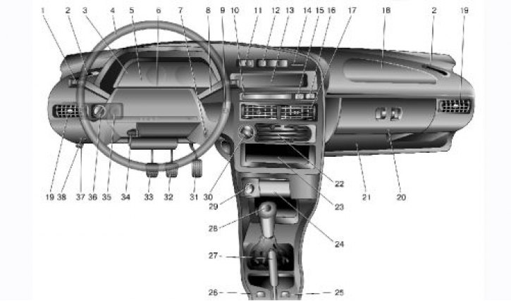
The following controls are located on the instrument panel (Fig. 1.7): 1 – direction indicator and headlight switch lever. 2 – front door glass blower nozzle. 3 – instrument cluster. 4 – steering wheel. 5 – horn switch.
Hazard warning switch
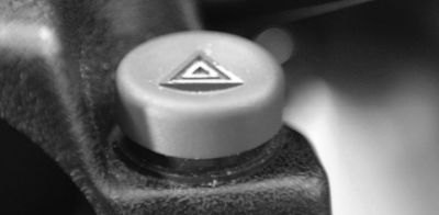
6 – Hazard warning light switch. When the button is pressed, the flashing light of all direction indicators and the control lamp in the instrument cluster is switched on. When the button is pressed again, the alarm is switched off:
7 – ignition switch (lock) (Fig. 1.8), combined with the anti-theft device, is located on the right side of the steering column. The key in the lock can occupy one of three positions:
- 0 – "off". All consumers are switched off, the key is removed. When the key is removed, the locking mechanism of the anti-theft device is activated. To ensure that the steering shaft is locked, turn the steering wheel to the right or left until it clicks. To turn off the anti-theft device, insert the key into the ignition switch and, slightly turning the steering wheel to the right and left, turn the key to position "I";
- I – "ignition". Ignition is on, key is not removed, steering is unlocked;
- II – "starter". The key is not removed, the steering is unlocked. This is achieved by turning the key clockwise, overcoming the spring force. In this position, the key is not fixed - to operate the starter, you need to hold it by hand. The ignition switch is equipped with a starter lock when the engine is running. To re-engage the starter after an unsuccessful start attempt, move the key from position "I" to position "0", and then back to position "II".

1.8. Ignition switch (lock)
Warning! Do not turn off the ignition or remove the key while driving - the steering will be locked and the car will become uncontrollable.
8 – windshield wiper and washer switch lever.
9 – the immobilizer alarm sensor is installed on a vehicle with a fuel injection system equipped with an electronic anti-theft system and is designed to transmit a secret code from the working code key through the immobilizer unit to the engine control controller.
10 – block of signal lamps of the on-board control system. The following lamps are installed in the block (Fig. 1.9):
1 – warning light for emergency drop in engine oil level. Lights up orange if the oil level in the engine crankcase has dropped below the "MIN" mark on the gauge;
2 – low washer fluid level indicator lamp. Lights up orange if there is less than 1 liter of washer fluid left in the tank;
3 – Low coolant level indicator lamp in the expansion tank. Lights up orange when the coolant level on a cold engine drops below the permissible limit;

1.9. Block of signal lamps of the on-board control system
Notes: Before adding oil to the engine check if it has leaked due to a leak in the engine lubrication system. Before adding fluid, check the engine cooling system for leaks.
4 – Door open indicator light. Lights up red when the car door is open;
5 – indicator lamp for malfunction of brake light or parking light. Lights up red in case of malfunction of brake light lamp when pressing the brake pedal or any parking light lamp when it is turned on;
6 – brake lining wear indicator light front brake pads. Lights up orange when you press the brake pedal and remains on until the ignition is turned off if the thickness of the front brake pads has decreased to 1.5 mm;
7 – Seat belt warning light. Lights up red if the driver's seat belts are not fastened.
11 – External lighting switch
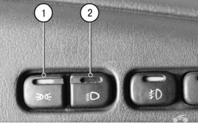
11 – External lighting switch. The switch block contains two mechanically connected switches:
- side light switch 1. By successively pressing the switch button, the side light in the headlights and in the rear lights is turned on and off; when the side light is on, a control lamp with a green light filter lights up in the button;
- headlight switch 2. When you press the switch key (fixed position) the headlights are turned on. Pressing the button again turns the headlights off.
Note: The mechanical connection between both switches eliminates the possibility of turning on the headlights without first turning on the parking lights and, conversely, does not allow turning off the parking lights when the headlights are on.

12 – key switch block
12 – the key switch block includes the following:
- switch 1 of the front fog lights. The fog lights are turned on by pressing the switch button while the side light switch button is pressed, and the indicator lamp in the button lights up at the same time. Pressing the button again turns the fog lights off;
- switch 2 rear fog lights. When you press the switch button, the rear fog lights turn on if the outside lights are on. When you press the button again, the rear fog lights turn off;
- switch 3 for heating the rear door glass. When you press the switch button, the glass heating turns on, and the control lamp in the button lights up at the same time. When you press the button again, the heating turns off.

13 – trip computer
13 – trip computer, installed on some of the vehicles produced, is designed to measure, accumulate and display on a digital display one of the following parameters:
- current fuel consumption;
- average total fuel consumption;
- average speed of movement;
- the path traveled;
- current time;
- travel time.
14 – plug.
15 – Anti-lock braking system (ABS) control lamp. Installed instead of the plug if the car is equipped with an anti-lock braking system.
16 – Airbag status indicator lamp. Installed instead of the plug if the car is equipped with an airbag.
17 – central nozzles of the ventilation and heating system.
18 – Upper storage compartment lid. To access the upper storage compartment, with the lower storage compartment lid open, press the upper lid lock lever.
Note: The lock lever is located at the top of the lower glove compartment recess.
19 – side nozzle of the ventilation and heating system of the passenger compartment.
20 – Lower glove compartment lid. To open it, press the handle of the locks to the handle. If the outside lighting is on, a special lamp illuminates the inside of the glove compartment.
21 – magazine shelf.
22 – ventilation and heating system control panel.
The original can be seen on the website vazbook.ru
23 – socket for radio equipment. Provides for installation of radio equipment that meets international standards in terms of size and mounting method.
24 – front ashtray.
25 – Right front seat heating switch.
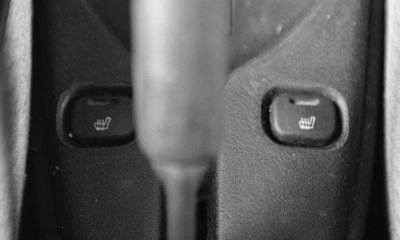
25 – Right front seat heating switch.
26 – Left front seat heating switch.
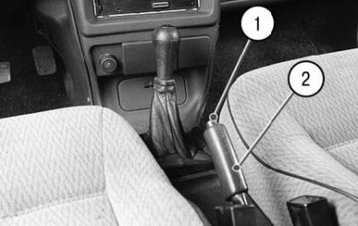
27 – parking brake lever.
27 – Parking brake lever. To brake the car with the parking brake, lift lever 2 all the way up – the red indicator lamp in the instrument cluster will light up. To release the brakes, pull the lever up a little, press button 1 on the end of the lever handle and lower it all the way down – the indicator lamp should go out.
28 – gear shift lever.
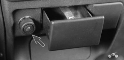
29 – cigarette lighter
29 – Cigarette lighter. To use the cigarette lighter, press the socket until it locks into place and release. After about 20 seconds, the socket automatically returns to its original position, ready for use.
30 – heater electric fan switch.
31 – accelerator pedal.
32 – brake pedal.
33 – clutch pedal.
34 – steering column angle adjustment handle.

35 – Instrument lighting switch
35 – Light switch instrument panels. By turning the handle, you can adjust the brightness of the instrument lighting and switch backlight lamps if the external lighting is on.

36 – headlight range control handle
36 – headlight corrector control handle. By turning the handle, the angle of the headlight beam is adjusted in such a way as to avoid blinding oncoming drivers. The positions of the corrector handle correspond to the following vehicle loading options:
- 0 – one driver;
- 1 - all seats are occupied;
- 2 – all seats are occupied and cargo is in the luggage compartment;
- 3 – one driver and cargo in the luggage compartment.
- 37 – hood lock drive lever.
- 38 – socket for connecting a portable lamp.