




Direction indicator wiring diagram
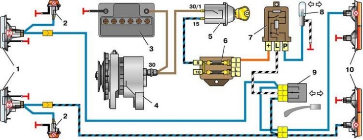
1 – sidelights; 2 – side direction indicators; 3 – battery; 4 – generator; 5 – ignition switch; 6 – fuse box; 7 – turn signal relay; 8 – direction indicator lamp; 9 – direction indicator switch; 10 – rear lights
Data for verification
| Cycles per minute at normal load 46 W: | |
| - at nominal voltage and 20°C | 85±15 |
| – at a voltage of 15 V and 40°C, no more | 120 |
| – at a voltage of 10.8 V and -20°C, not less | 60 |
The RS-491 type flasher relay is designed to produce an intermittent light signal of the direction indicators. It is mounted under the instrument cluster on a bolt welded to the wall of the air intake box. A faulty flasher relay cannot be repaired and should be replaced with a new one. To replace it, you must first remove the instrument cluster.
Information copied from the portal VazBook.ru