




Repair of electrical equipment of engine VAZ-2101 Zhiguli

Battery design
The 6ST-55 battery consists of six 2 V cells connected in series. Each cell is placed in a separate compartment and consists of positive and negative plates separated by...
The 6ST-55 battery consists of six 2 V cells connected in series. Each cell is placed in a separate compartment and consists of positive and negative plates separated by...

Keeping the battery in good working order
Checking the electrolyte level The electrolyte level should be 5-10 mm above the upper edge of the separators and not rise above the lower edge of the filler neck. During battery...
Checking the electrolyte level The electrolyte level should be 5-10 mm above the upper edge of the separators and not rise above the lower edge of the filler neck. During battery...

Possible faults of the battery
Possible battery malfunctions, their causes and troubleshooting methods are given in Table 24.
Possible battery malfunctions, their causes and troubleshooting methods are given in Table 24.

The device and operation of the generator
The vehicles are equipped with a three-phase alternating current generator G221 (Fig. 152). The main parts of the generator are the stator 19 with two covers and made of aluminum...
The vehicles are equipped with a three-phase alternating current generator G221 (Fig. 152). The main parts of the generator are the stator 19 with two covers and made of aluminum...
Rules for checking and operating the generator
When operating, servicing and repairing the generator, the following rules must be observed, violation of which may result in damage to the voltage regulator or rectifier valves....
When operating, servicing and repairing the generator, the following rules must be observed, violation of which may result in damage to the voltage regulator or rectifier valves....

Possible malfunctions of the generator set
Possible generator set malfunctions, their causes and methods of elimination are given in Table 25.
Possible generator set malfunctions, their causes and methods of elimination are given in Table 25.

Generator Checks
Checking the generator on the car If the battery charge indicator light is on when the engine is running, then the generator's serviceability is roughly determined as follows: by...
Checking the generator on the car If the battery charge indicator light is on when the engine is running, then the generator's serviceability is roughly determined as follows: by...

Generator repair
Disassembly After unscrewing the fastening screws, remove the brush holder 2 (Fig. 157) with the brushes. Unscrew the nuts of the tie bolts 14 and remove the generator cover 11...
Disassembly After unscrewing the fastening screws, remove the brush holder 2 (Fig. 157) with the brushes. Unscrew the nuts of the tie bolts 14 and remove the generator cover 11...

The device and operation of the voltage regulator
Voltage regulator (PH) - two-stage, type PP380, has 2 fixed contacts on posts 7 and (Fig. 159) and between them a vibrating contact installed on anchor 10. The contact of the...
Voltage regulator (PH) - two-stage, type PP380, has 2 fixed contacts on posts 7 and (Fig. 159) and between them a vibrating contact installed on anchor 10. The contact of the...

Checking and adjusting the voltage regulator
Inspection and operation rules To avoid damaging the regulator during testing and operation, the following rules must be observed. You must not mix up the wires connected to the...
Inspection and operation rules To avoid damaging the regulator during testing and operation, the following rules must be observed. You must not mix up the wires connected to the...
Troubleshooting a Voltage Regulator
If the car battery is constantly overcharged, then, without removing the voltage regulator, check it under the following conditions: the battery must be fully charged; all...
If the car battery is constantly overcharged, then, without removing the voltage regulator, check it under the following conditions: the battery must be fully charged; all...
Voltage Regulator Repair
The voltage regulator should be repaired only in exceptional cases, in other cases it is recommended to replace it. The following operations are allowed for the regulator repair....
The voltage regulator should be repaired only in exceptional cases, in other cases it is recommended to replace it. The following operations are allowed for the regulator repair....
Battery charge indicator lamp relay
The RS-702 relay is used to turn on the control lamp on the instrument panel when the generator voltage is insufficient to charge the battery. The relay is installed in the engine...
The RS-702 relay is used to turn on the control lamp on the instrument panel when the generator voltage is insufficient to charge the battery. The relay is installed in the engine...

The structure and operation of the starter
The ST221 starter (Fig. 161) is a four-pole, four-brush DC electric motor with mixed excitation, with electromagnetic engagement of the drive gear and remote control. The covers...
The ST221 starter (Fig. 161) is a four-pole, four-brush DC electric motor with mixed excitation, with electromagnetic engagement of the drive gear and remote control. The covers...
Possible faults starter
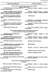
Possible starter malfunctions, their causes and methods of elimination are given in Table 26.
Possible starter malfunctions, their causes and methods of elimination are given in Table 26.

Checking the starter on the stand
To ensure the efficiency of the starter, it is necessary to test its electrical and mechanical characteristics on a bench. The electrical circuit for testing the starter on a...
To ensure the efficiency of the starter, it is necessary to test its electrical and mechanical characteristics on a bench. The electrical circuit for testing the starter on a...
Disassembling and assembling the starter
Starter malfunctions or damage are eliminated by replacing faulty parts. The only repair operation that can be performed is turning the collector. Disassembly Unscrew the nut on...
Starter malfunctions or damage are eliminated by replacing faulty parts. The only repair operation that can be performed is turning the collector. Disassembly Unscrew the nut on...
Checking the technical condition and repairing the starter
Anchor Check with a megohmmeter or a lamp powered by 220 V to see if the anchor winding is shorted to ground. Voltage is supplied through the lamp to the collector plates and to...
Anchor Check with a megohmmeter or a lamp powered by 220 V to see if the anchor winding is shorted to ground. Voltage is supplied through the lamp to the collector plates and to...

The structure and operation of the ignition system
The ignition system diagram (Fig. 164) consists of two circuits: low voltage or primary circuit, which includes power sources 6 and 7, ignition switch 8, capacitor 4, primary...
The ignition system diagram (Fig. 164) consists of two circuits: low voltage or primary circuit, which includes power sources 6 and 7, ignition switch 8, capacitor 4, primary...

Checking the ignition system components
Distributor Before installing the ignition distributor on the stand, check the condition of the breaker contacts, whether the lever with the movable contact is jammed, as well as...
Distributor Before installing the ignition distributor on the stand, check the condition of the breaker contacts, whether the lever with the movable contact is jammed, as well as...

Possible malfunctions of the ignition system
Possible malfunctions of the ignition system, their causes and methods of elimination are given in Table 28.
Possible malfunctions of the ignition system, their causes and methods of elimination are given in Table 28.
This section is available on russian, bulgarian, belarusian, ukrainian, serbian, croatian, romanian, polish, slovak, hungarian
More articles from other manuals on VAZ cars:
➠ Electrical equipment: Engine electrics VAZ-2115 (1997-2012)
➠ Power unit: Engine repair VAZ-2107 (1982-2012)
➠ Power unit: Engine repair VAZ-2112 (1999-2007)
➠ Electrical equipment: Engine electrics VAZ-21213 (1994-2006)
➠ Power unit: Engine repair VAZ-2106 (1976-2006)
➠ Electrical equipment: Engine electrics VAZ-2115 (1997-2012)
➠ Power unit: Engine repair VAZ-2107 (1982-2012)
➠ Power unit: Engine repair VAZ-2112 (1999-2007)
➠ Electrical equipment: Engine electrics VAZ-21213 (1994-2006)
➠ Power unit: Engine repair VAZ-2106 (1976-2006)
Share with friends:
- General information
- Vehicle description
- Vehicle device
- Vehicle operation
- Maintenance
- Main malfunctions
- Applications
- Power unit
- Engine repair
- Cooling and lubrication system
- Supply system
- Transmission
- Clutch
- Transmission
- Cardan gear
- Rear axle
- Chassis
- Front suspension
- Rear suspension
- Steering
- Brake system
- Body
- Exterior
- Interior
- Electrical equipment
- Engine electrics
- Equipment and devices
- General information
- Specifications
- Operation and maintenance
- Power unit
- Engine repair
- Cooling system
- Lubrication system
- Power and exhaust system
- Ignition system
- Engine electrics
- Transmission
- Clutch
- Car gearbox
- Cardan gear
- Rear axle
- Chassis
- Car suspension
- Steering
- Brake system
- Body
- Exterior
- Interior
- Doors and locks
- Electrical equipment
- Equipment and devices
- Lighting and signaling